Skip to main contentSkip to navigationSkip to contactAccessibility (Alt+A)
EmersonEIMS — Reliable Power. Without Limits.
INDUSTRIES
CONTACT
Get Quote

B2BEmersonEIMS serves commercial, industrial, healthcare, telecom, hospitality, government & contractor clients.• Engineering-led • SLA-backed • Documented commissioning

Talk to an engineerWhatsApp+254 768 860 665

Services Directory

View all services →

Power & Generators

  • Cummins Generators (2-yr warranty)
  • Generator Repairs & Maintenance
  • ATS / Changeovers
  • Generator Sales
  • Generator Rental
  • Generator Installation
  • Generator Spare Parts
  • Workshop Repairs & Fabrication
  • Power Interruption Solutions

Renewable & UPS

  • Solar Energy Solutions
  • Commercial / Industrial Solar
  • Solar System Sizing
  • Solar Genius Pro™
  • UPS Systems
  • UPS Lab
  • Solar / UPS Hub
  • Borehole Pumps

Electrical & HVAC

  • Distribution Boards & Panels
  • Motor Rewinding
  • Motors & Drives
  • High-Voltage Systems
  • Diesel Automation
  • Industrial Controls
  • Steel Fabrication
  • AC / HVAC Installation

Specialised & AI Suites

  • Hospital Incinerators
  • Incinerator Construction Guide
  • Building Engineering Suite
  • EIMS PRO Workspace
  • AquaScan Pro™
  • Generator Oracle™
  • Plant & Equipment Oracle
  • Diagnostics Hub
  • Troubleshooting Wizard

Maintenance Hubs

  • Generator Maintenance
  • Solar Maintenance
  • HVAC Maintenance
  • Borehole Maintenance
  • Electrical Maintenance
  • Motors Maintenance
  • Incinerator Maintenance
  • Fabrication & Welding

Resources & Tools

  • Repair Centre — 60 free guides
  • Spare Parts Marketplace
  • Sectors We Serve
  • Brands We Service
  • All Engineering Tools
  • Resources & Learning Hub
  • Knowledge Base
  • Technical Bible
  • Power Calculators
  • Fault Code Database
  • Blog & Articles
  • FAQ
  • Emergency Response Guide

Service Areas

  • All Kenya — 47 Counties
  • Nairobi
  • Mombasa
  • Kisumu
  • Nakuru
  • Kiambu
  • All Service Locations
  • East Africa
  • Kampala, Uganda
  • Dar es Salaam, Tanzania
  • Kigali, Rwanda
  • Juba, South Sudan
  • Site Directory — every page
EMERSONEiMS

Engineering-grade reliability for East Africa's critical infrastructure. Power systems built to perform.

  • X↗
  • Facebook↗

Company

  • About Us
  • All Services
  • Prices & Costs
  • Book a Service
  • Project Gallery
  • Case Studies
  • Industries Served
  • Careers
  • Contact Us

Quick Links

  • Generator Sales
  • Solar Energy
  • Diagnostic Suite
  • Solar / UPS Hub
  • Generator Oracle
  • Knowledge Base
  • FAQ

Contact

  • Nairobi HQEmbakasi, off Airport North Road, Nairobi
    (Near KEMSA Head Office)
  • Department Emails
    • General Inquiriesinfo@emersoneims.com
    • Service Coordinationemersoneimservices@emersoneims.com
    • Generator Deskgenerators@emersoneims.com
    • Solar & UPS Desksolar@emersoneims.com
    • Sally — Direct Accountsally@emersoneims.com
  • Phone
    +254782914717
    +254768860665

© 2026 Emerson EiMS. All rights reserved.

PROTECTED BY GENERATOR ORACLE / EMERSONEIMS
Privacy PolicyTerms of Service
ENGINEERED IN NAIROBI, KENYA

Keyboard Shortcuts

  • Alt + A: Open accessibility settings
  • Tab: Navigate to next element
  • Shift + Tab: Navigate to previous element
  • Enter or Space: Activate buttons and links
  • Escape: Close dialogs and menus
  • Arrow keys: Navigate within menus and sliders
  • Home: Go to beginning of list
  • End: Go to end of list
  1. Home
  2. /
  3. Generators
  4. /
  5. Workshop Repairs & Fabrication
EmersonEIMS Workshop and Engineering Services

Generator, Engine, Electrical and Industrial Workshop Services in Kenya

Restore it. Rebuild it. Fabricate it. Keep your operations running.

From generator radiators, starters, alternators, injectors and turbochargers to motor rewinding, UPS repairs, pump overhauls, fuel systems and custom fabrication, EmersonEIMS provides coordinated workshop and field engineering services for businesses across Kenya.

Equipment can be delivered to our workshop, collected where arrangements are available, or sent through a suitable courier or transport service and returned the same way after repair.

  • ✔Generator, engine and electrical repairs
  • ✔Industrial and mechanical workshop services
  • ✔Custom steel and equipment fabrication
  • ✔Nationwide component receipt and dispatch
  • ✔Inspection and quotation before major work
  • ✔Repair testing and documented handover
Send equipment photos on WhatsAppCall the workshopRequest a repair assessment

Jump to a service

  • Cooling Systems
  • Starters & Alternators
  • Motor Rewinding
  • Injectors & Fuel Pumps
  • Injection Pumps
  • Turbochargers
  • Engine Overhauls
  • UPS Repairs
  • Pump Repairs
  • Generator Canopies
  • Exhaust Systems
  • Fuel Tanks
  • Fuel Automation
  • Generator Plinths
  • Security Cages
  • Hammer Mills
  • Industrial Grinders

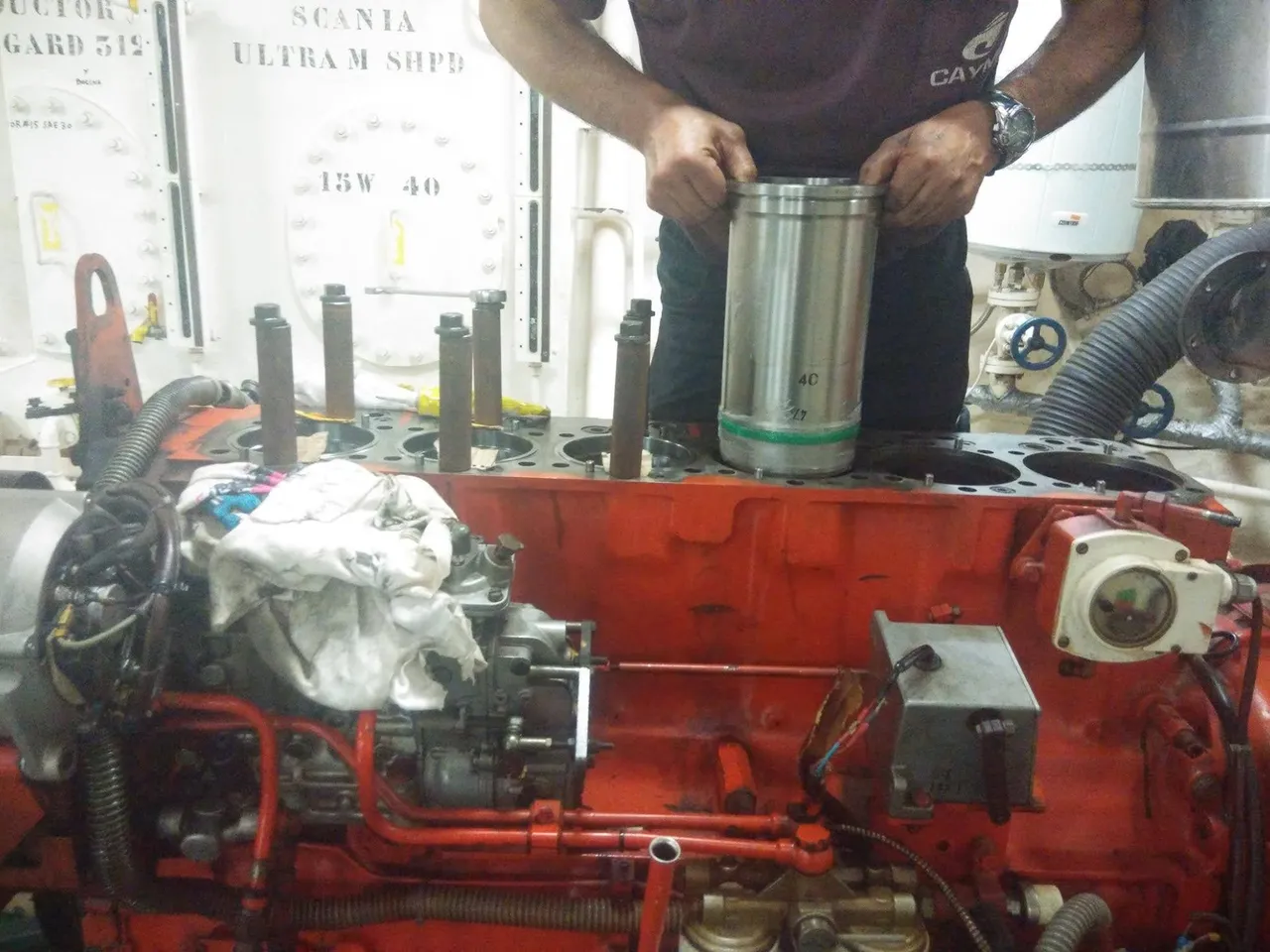
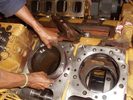
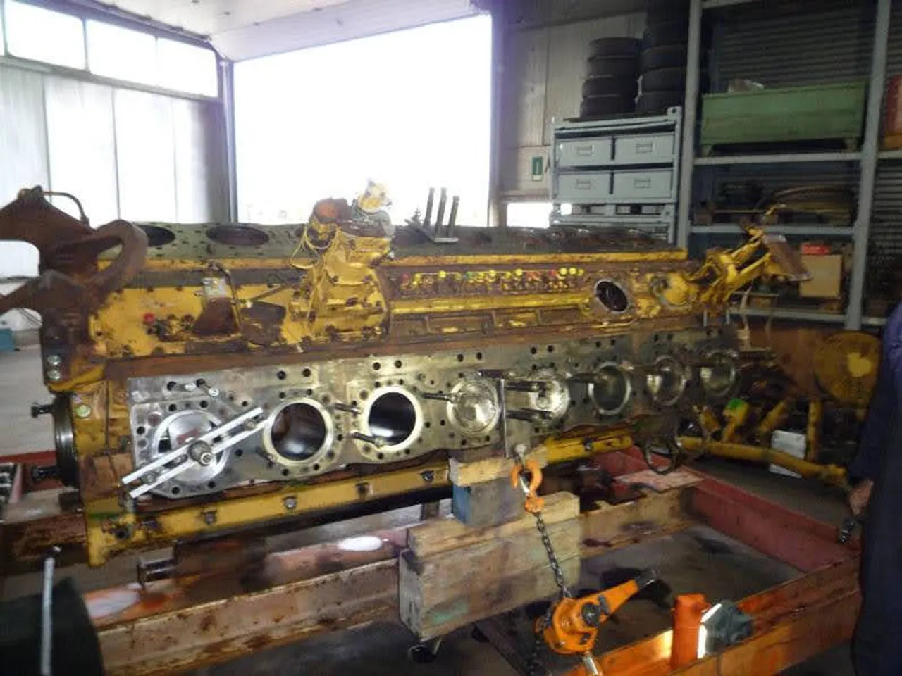
Inside the workshop

Engine strip-down, liner and block work photographed during actual jobs.

EmersonEIMS technician lowering a new cylinder liner into a stripped six-cylinder diesel engine block during an overhaul
Cylinder liner being fitted to a stripped block
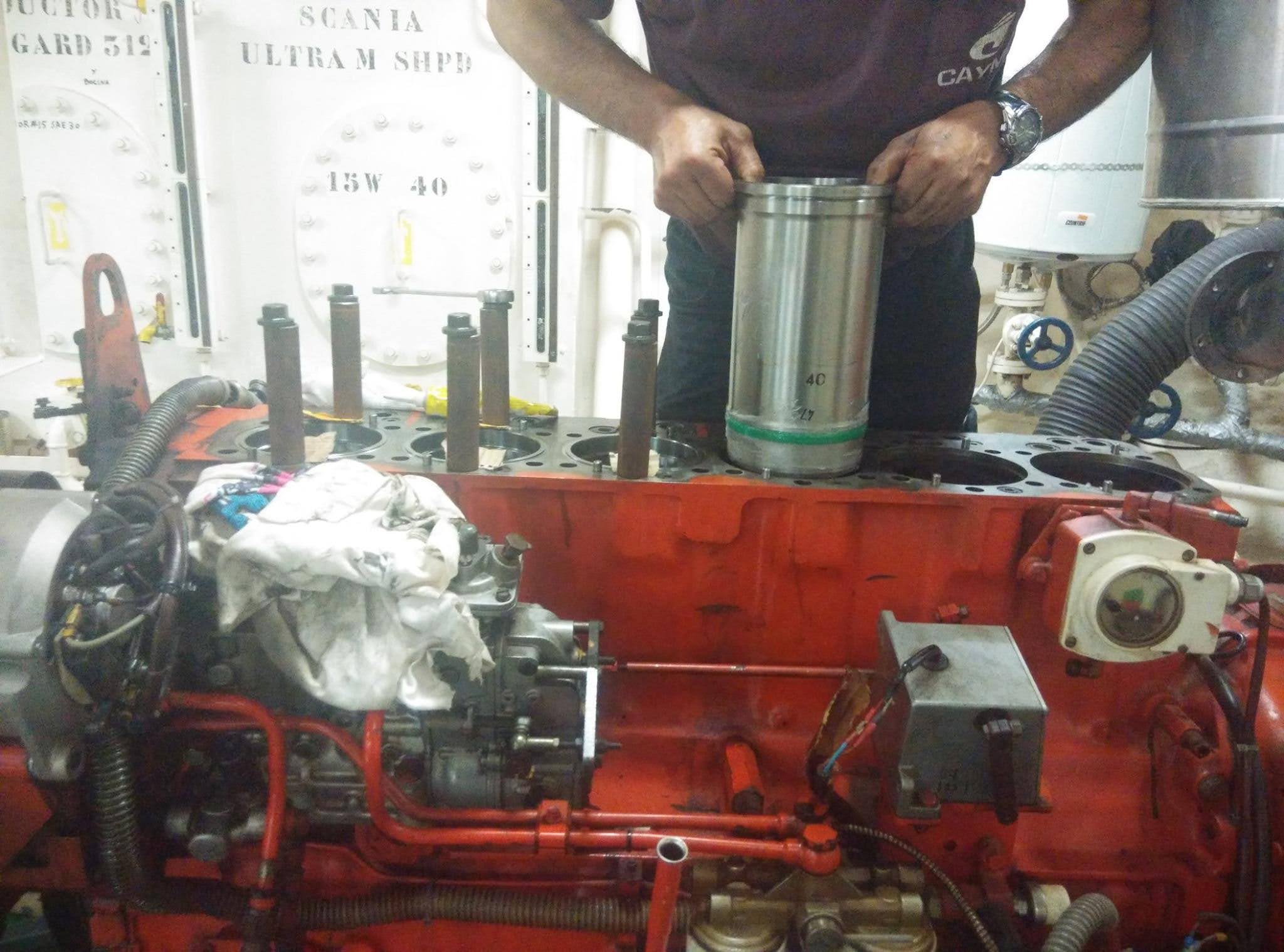
Technician handling a numbered cylinder liner over an open engine block, with bores and head-bolt holes visible during a generator engine overhaul
Liners marked and matched to their bores
Large diesel engine block stripped to the bare casting and supported on timber and lifting gear in the EmersonEIMS workshop
Block stripped for measurement and rebuild

Generator & Engine Component Repairs

Cooling, starting, charging, fuel and air systems — repaired at component level rather than replaced wholesale.

Radiator & Cooling System Repairs

Overheating destroys engines faster than almost any other fault, and on standby sets it usually appears the first time the machine is asked to take real load. We inspect, pressure-test and repair generator and industrial-engine cooling systems rather than condemning a radiator on appearance.

What the work covers

  • •Pressure testing to locate leaks under working conditions
  • •Core cleaning, flushing and blockage assessment
  • •Tube, core and end-tank repair where the core is serviceable
  • •Radiator cap and thermostat testing
  • •Hose, clamp and fan-drive inspection
  • •Coolant condition and inhibitor assessment
  • •Cooling-system troubleshooting on running sets

Symptoms we see

  • Coolant leakage
  • High-temperature shutdown under load
  • Blocked or fin-damaged core
  • Corroded or split end tanks
  • Contaminated coolant
  • Weak airflow through the radiator
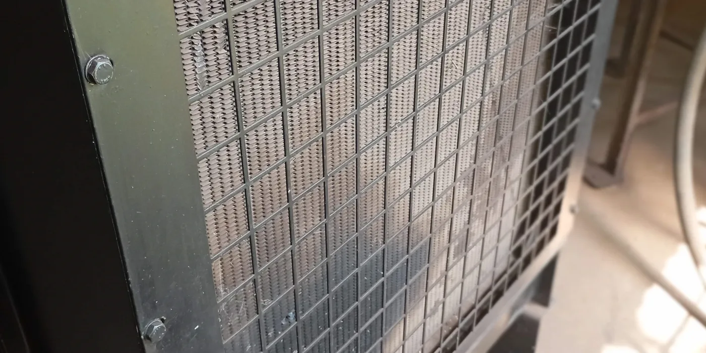
Close-up of a generator radiator fin-and-tube core behind its protective mesh guard, the surface loaded with dust that restricts cooling airflow
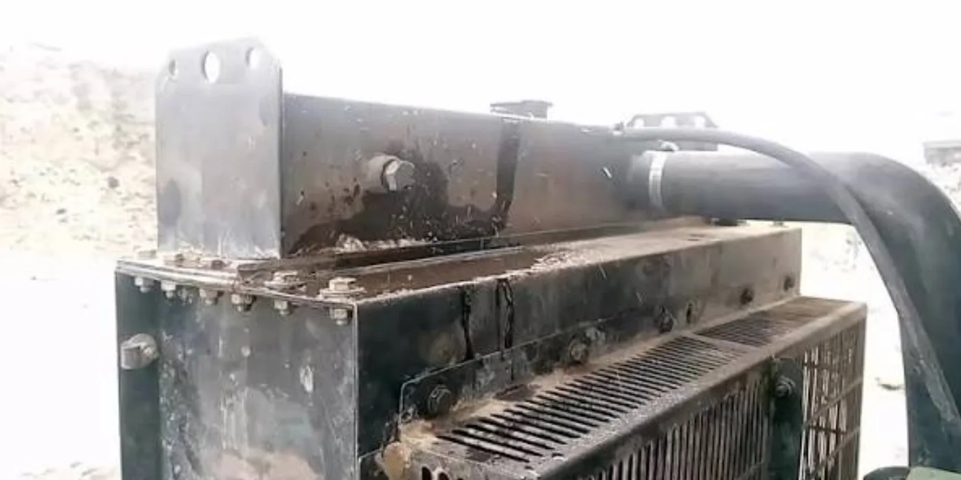
Top header tank and fabricated side plates of a large industrial generator radiator during workshop inspection and cleaning

Understanding it

A generator radiator is a heat exchanger: hot coolant from the engine passes through a matrix of thin tubes bonded to fins, and the engine-driven fan pulls air across that matrix to carry the heat away. It has to reject the full waste heat of the engine — roughly as much energy as the set delivers as electricity — every second it runs on load. When it cannot, cylinder-head and liner temperatures rise and the damage that follows is measured in whole engines, not radiators.

Full technical guide — causes, repair, parts & prevention+
Why it fails — common causes
Airside blockage
Dust, chaff, insects and oily film bridge the fins and choke airflow. This is the single most common cause on Kenyan sites — dusty yards, grass, and cooling air drawn through an unfiltered louvre. The core looks intact but cannot breathe.
Internal scaling and silting
Hard water, plain water without inhibitor, and mixed coolants leave scale inside the tubes. Scale is an insulator; a thin layer collapses heat transfer and blocks the smaller tubes entirely.
Corrosion and electrolysis
Missing supplemental coolant additive lets the tube-to-fin bond corrode. Stray current through the coolant (a bad earth) pits the tubes electrolytically, producing pinhole leaks.
Mechanical and thermal fatigue
Vibration cracks the header-tank seams and solder joints; repeated heat cycling splits end tanks. A missing or wrong-rated pressure cap raises system pressure and finds the weakest seam.
Fan and shroud faults
A slipping fan belt, a failed viscous drive or a missing shroud all reduce airflow and are frequently mistaken for a blocked core.
How we repair it
  1. 1.Pressure-test the cold system to locate leaks before stripping anything — a leak found under pressure is a leak, a wet patch is a guess.
  2. 2.Remove the radiator, drain and inspect the core, tanks and seams.
  3. 3.Rod-out and back-flush the tubes; chemically de-scale where internal fouling is found.
  4. 4.Repair serviceable cores — re-solder or seal leaking tubes, or block off a small number of dead tubes within the derating limit; recore where the matrix is beyond repair.
  5. 5.Repair or replace end tanks and header seams; renew the filler neck and test the pressure cap.
  6. 6.Renew hoses, clamps and the thermostat as required, and check the fan, belt and shroud before refit.
How we test it before handover
  • ✓Pressure test to the system rated pressure and hold — no drop permitted.
  • ✓Flow check to confirm the core is not internally restricted.
  • ✓Run the set up to operating temperature and verify it holds temperature on load, not just at idle.
  • ✓Confirm the thermostat opens at its rated temperature and the fan moves the expected air.
Parts & materials used
  • Radiator cores / recore kits
  • End tanks and header gaskets
  • Pressure caps rated to the system
  • Thermostats
  • Hoses, clamps and fan belts
  • Coolant and supplemental coolant additive (SCA)
How to prevent it happening again
  • →Clean the core on a schedule matched to the site — weekly in dusty or agricultural yards, not annually.
  • →Use the correct coolant with inhibitor, never plain water; top up with the same coolant, never mixed types.
  • →Fit and maintain intake louvres and keep the plant room free of grass and litter.
  • →Replace the pressure cap when it is due — it is the cheapest part on the engine and protects every seam.
  • →Fix a slipping belt or a bad earth immediately; both destroy radiators indirectly.
Request Radiator Inspection

Starter Motors & Charging Alternators

A set that will not crank, or one whose batteries are flat when it is finally needed, is usually a starting or charging fault rather than an engine fault. Both are repairable at component level.

What the work covers

  • •Starter solenoid testing and replacement
  • •Armature, commutator and brush servicing
  • •Bush, bearing and Bendix-drive inspection
  • •Charging alternator diagnosis — output, regulator and rectifier
  • •Diode and rectifier pack testing
  • •Bearing replacement and terminal repair
  • •No-load functional testing before return

Symptoms we see

  • Engine will not crank
  • Slow or intermittent cranking
  • Batteries flat after standing
  • Charge warning during running
  • Grinding on engagement
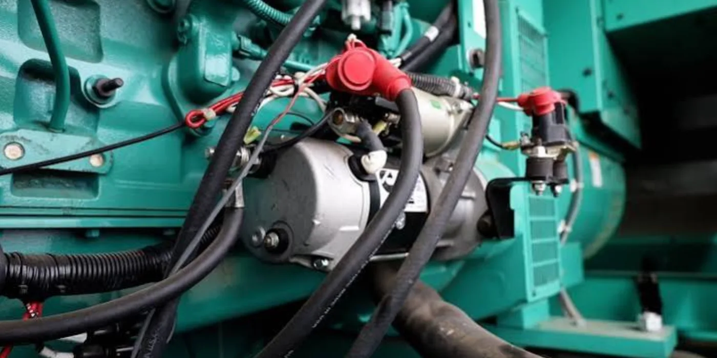
Starter motor and solenoid mounted on a Cummins generator engine, with battery cables and red terminal boots, before removal for overhaul
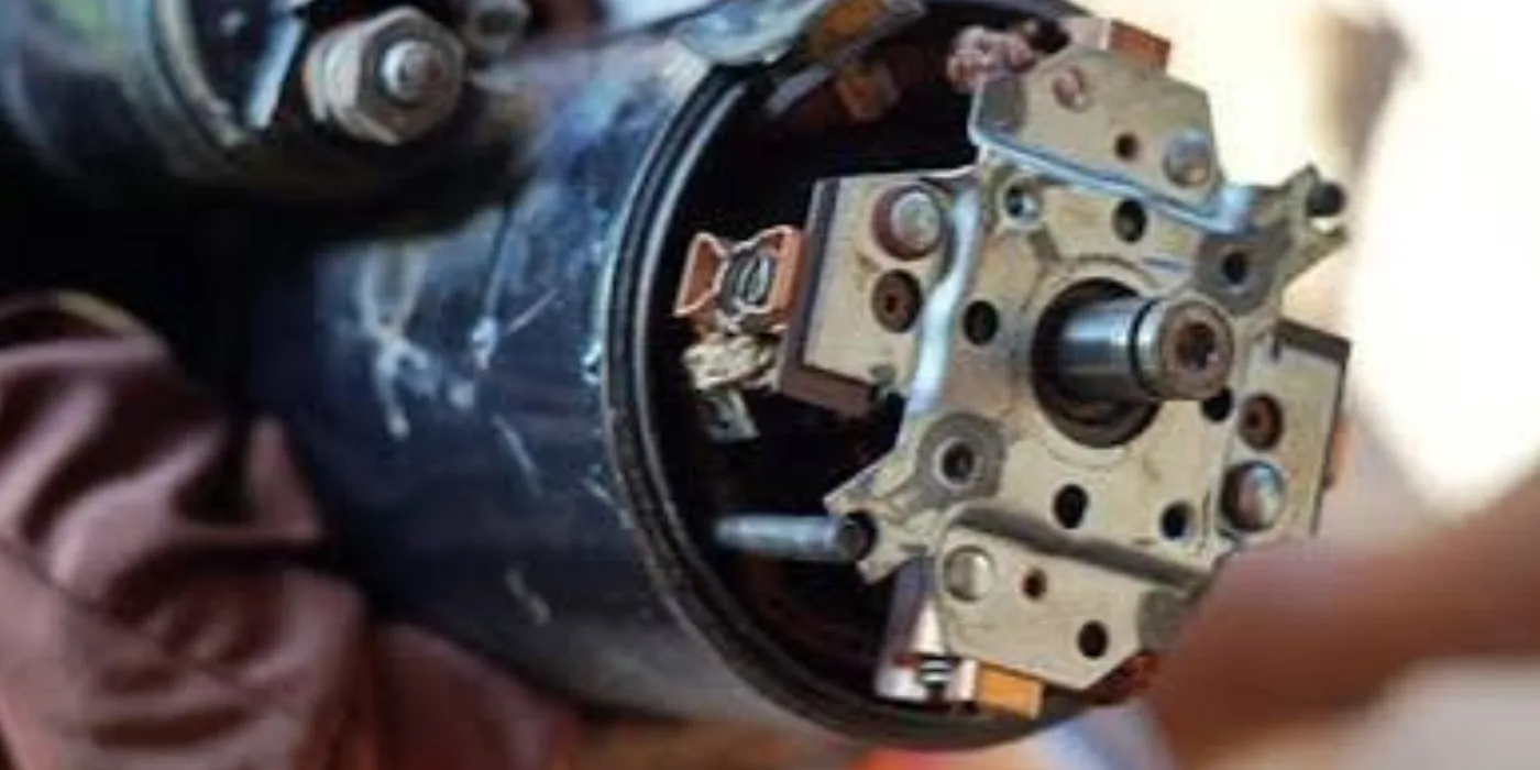
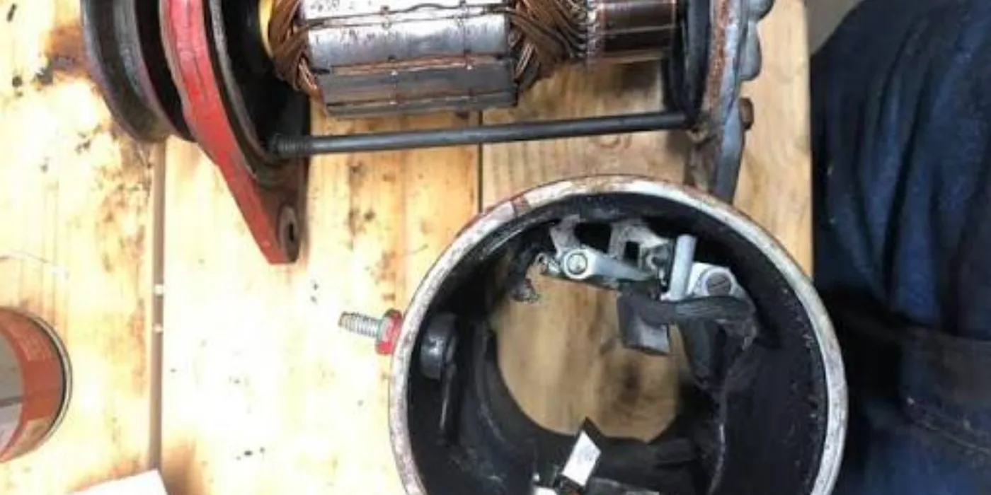
Starter motor components on the workshop bench during inspection and repair
Generator starting and charging components assessed on the bench at EmersonEIMS

Understanding it

The starter motor is a heavy series-wound DC motor that spins the engine fast enough to fire; the charging alternator keeps the starting batteries topped up while the set runs. Both are small next to the engine, but a standby set that will not crank, or whose batteries are flat on the day of an outage, has failed completely regardless of engine condition. Most "the generator won't start" call-outs end here, not in the engine.

Full technical guide — causes, repair, parts & prevention+
Why it fails — common causes
Worn brushes and commutator (starter)
Carbon brushes wear and the copper commutator glazes or grooves, so current cannot reach the armature. The starter clicks or spins weakly.
Failed solenoid or contacts
The solenoid both throws the pinion and switches the heavy current. Burnt contacts give a loud click with no crank — one of the most common single faults.
Bearing and bush wear
Worn end bushes let the armature rub the field poles; a dragging starter draws huge current and cranks slowly.
Bendix / pinion drive wear
A worn one-way clutch or chipped pinion grinds on the ring gear instead of engaging.
Charging faults (alternator)
A failed diode/rectifier pack, worn slip-ring brushes or a faulty regulator stops the batteries charging, so the set runs but the batteries die unnoticed until the next start fails.
Cabling and connections
Corroded battery terminals and undersized or loose cables mimic a failed starter — the classic misdiagnosis. Voltage drop under crank is the giveaway.
How we repair it
  1. 1.Confirm the battery and cabling first — measure voltage drop under crank; a good starter cannot work through a bad connection.
  2. 2.Bench-strip the starter: inspect armature, commutator, field coils and brushes.
  3. 3.Skim or undercut the commutator, fit new brushes, renew bushes/bearings and clean or replace the solenoid contacts.
  4. 4.Inspect the Bendix drive and pinion; renew if worn, and check the ring gear it meshes with.
  5. 5.For the charging alternator: test diodes/rectifier, slip rings, brushes and the regulator; renew the failed items and the bearings.
  6. 6.Reassemble to specification and clean all current-carrying faces — resistance is the enemy in a starting circuit.
How we test it before handover
  • ✓No-load bench test the starter for correct speed and current draw.
  • ✓Loaded/stall test where facilities allow, to prove torque and current are within limits.
  • ✓Test the charging alternator for rated output voltage and current across the speed range.
  • ✓On the set: confirm clean crank, and confirm charge voltage settles to the correct float once running.
Parts & materials used
  • Brush sets and brush holders
  • Solenoids and contact kits
  • Bushes, bearings and thrust washers
  • Bendix / one-way clutch drives
  • Rectifier/diode packs and voltage regulators
  • Slip rings and field service items
How to prevent it happening again
  • →Keep starting batteries on a maintained float charge between runs — the biggest single cause of failed standby starts.
  • →Clean and grease battery terminals; renew corroded or undersized cables.
  • →Exercise standby sets under load regularly so charging faults surface before an emergency.
  • →Do not crank in long bursts — it overheats the starter; investigate why it will not fire instead.
Send Starter or Alternator Details

Injector Nozzle Testing & Repair

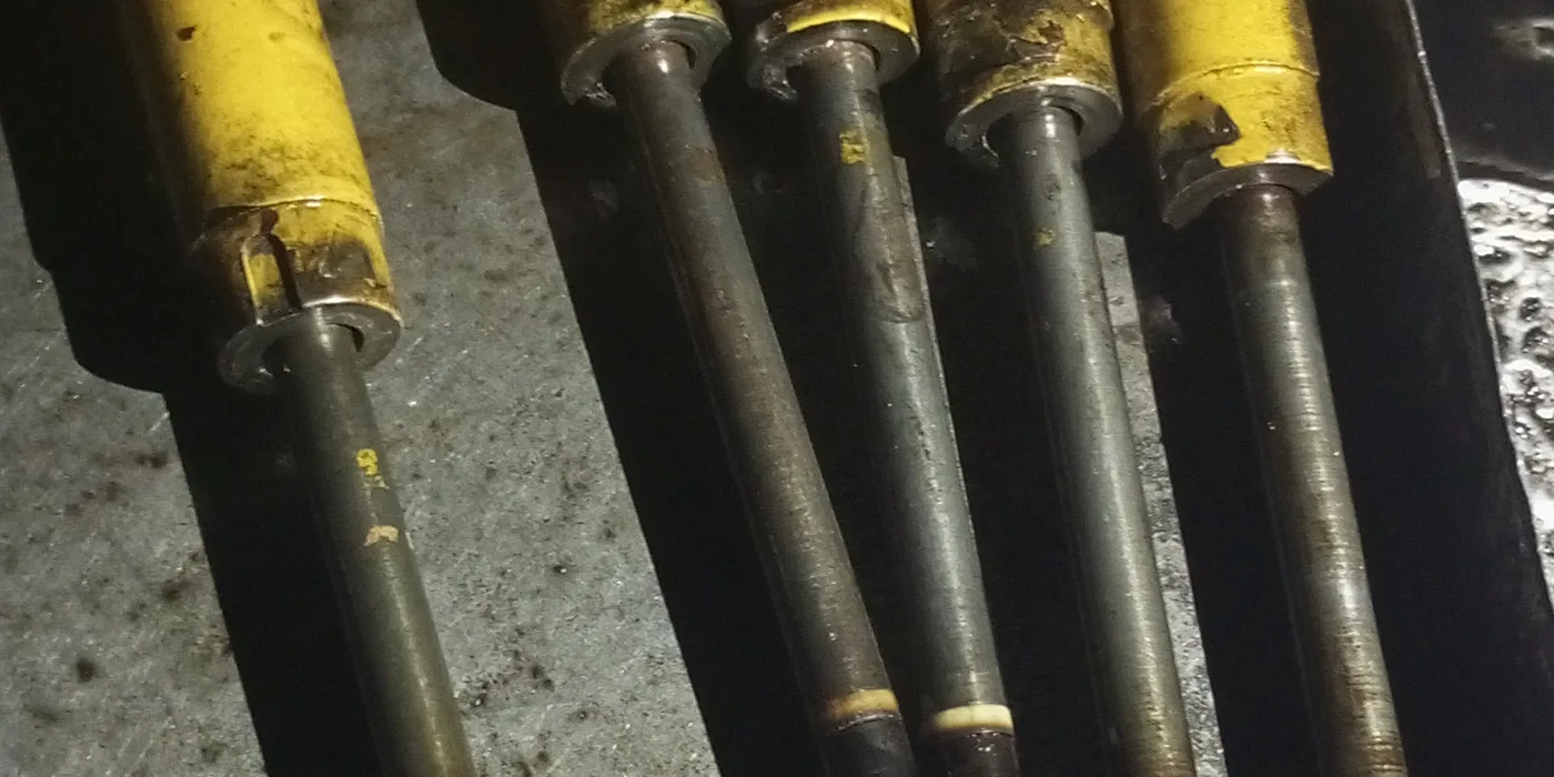
Injector faults show as smoke, rough running and poor load acceptance, and they are frequently misdiagnosed as engine wear. Injectors are assessed on test rather than by symptom alone.

What the work covers

  • •Spray-pattern examination
  • •Opening-pressure assessment
  • •Leak-back assessment
  • •Nozzle cleaning and carbon removal
  • •Nozzle-tip replacement where appropriate
  • •Cylinder-to-cylinder comparison
  • •Injector calibration where the equipment is available

Symptoms we see

  • Black smoke
  • Rough or uneven running
  • Hard starting
  • Knocking on one cylinder
  • High fuel consumption
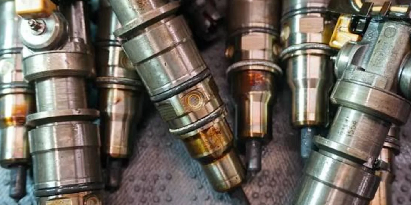
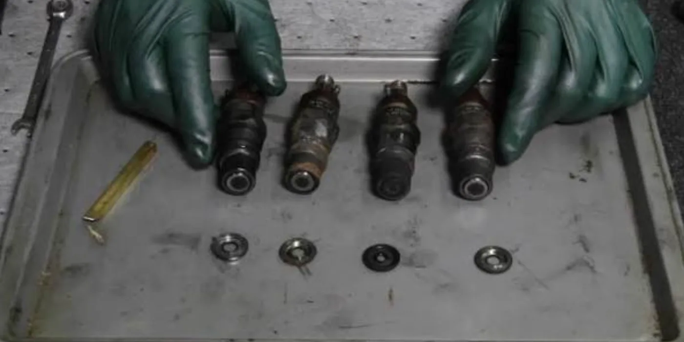
Row of diesel fuel injectors removed from a generator engine and laid out on the bench for testing at EmersonEIMS
Diesel injectors under inspection during nozzle testing and cleaning
Injector nozzle components assessed on the workshop bench
Diesel injector detail during spray-pattern and opening-pressure testing

Understanding it

A diesel injector atomises fuel into the combustion chamber at very high pressure, in a precise spray pattern and at an exact moment. The nozzle tip has microscopic spray holes; when they wear, coke up or the needle no longer seats, the fuel dribbles instead of atomising. The result is smoke, wasted fuel and burnt pistons — and it is often misdiagnosed as engine wear.

Full technical guide — causes, repair, parts & prevention+
Why it fails — common causes
Dirty fuel and water
Abrasive particles wear the needle and seat; water corrodes them and causes the tip to erode. Poor fuel filtration is the root cause of most injector failure in the field.
Carbon build-up (coking)
Idling, poor combustion and low-quality fuel coke the spray holes, distorting the pattern so one side of the chamber is over-fuelled.
Worn nozzle and needle
The needle-to-seat fit is a lapped, matched pair. Wear raises leak-back, drops opening pressure and ruins the spray.
Wrong or weak opening pressure
A tired spring or wrong shim opens the nozzle early or late, mis-timing delivery.
Over-heating from a stuck or leaking injector
A leaking injector washes the cylinder and can hole a piston — the most expensive downstream consequence.
How we repair it
  1. 1.Remove the injectors and test each on the injector tester: spray pattern, opening pressure, chatter and leak-back.
  2. 2.Dismantle, ultrasonically clean and de-carbon the nozzle and body.
  3. 3.Replace the nozzle tip (needle-and-seat assembly) where it is worn — these are matched, lapped parts, not cleaned back to new.
  4. 4.Reset opening pressure with the correct shim/spring and re-test.
  5. 5.Renew copper sealing washers and confirm cylinder-to-cylinder consistency before refit.
How we test it before handover
  • ✓Spray-pattern test — clean, sharp, symmetrical spray from every hole.
  • ✓Opening-pressure test to the manufacturer's specification.
  • ✓Leak-back / dry-seat test to confirm the needle holds pressure.
  • ✓On the engine: confirm smoke clears and each cylinder contributes evenly.
Parts & materials used
  • Nozzle tips (needle-and-seat assemblies)
  • Injector springs and shims
  • Copper sealing washers and sealing rings
  • Nozzle nuts and internal parts
How to prevent it happening again
  • →Maintain fuel filtration — the primary defence; change filters on schedule and drain water separators.
  • →Keep fuel clean and dry in storage; water in the day tank ruins injectors and pumps together.
  • →Avoid prolonged light-load idling, which cokes nozzles.
  • →Test injectors at overhaul rather than assuming — a marginal injector destroys a piston cheaply.

Worth knowing: Some nozzles are beyond economic repair and replacement is the better outcome — we say so at inspection rather than after the work.

Book Injector Testing

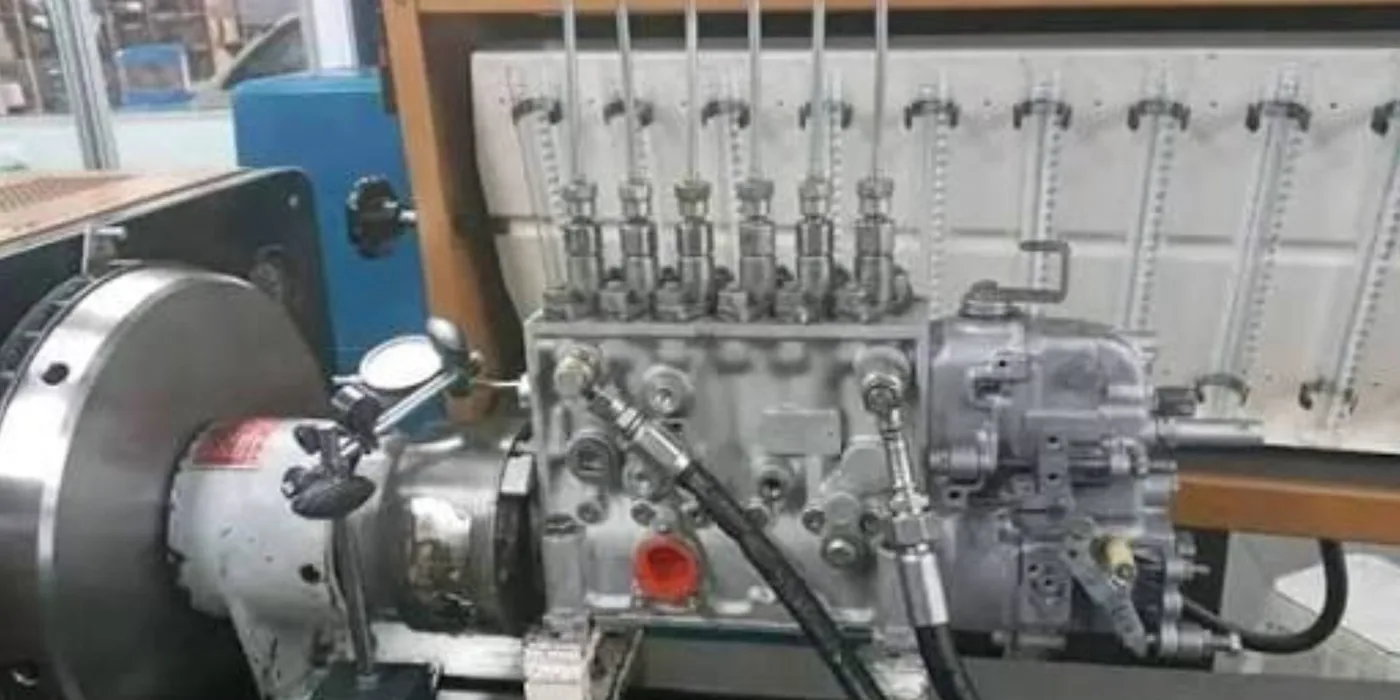
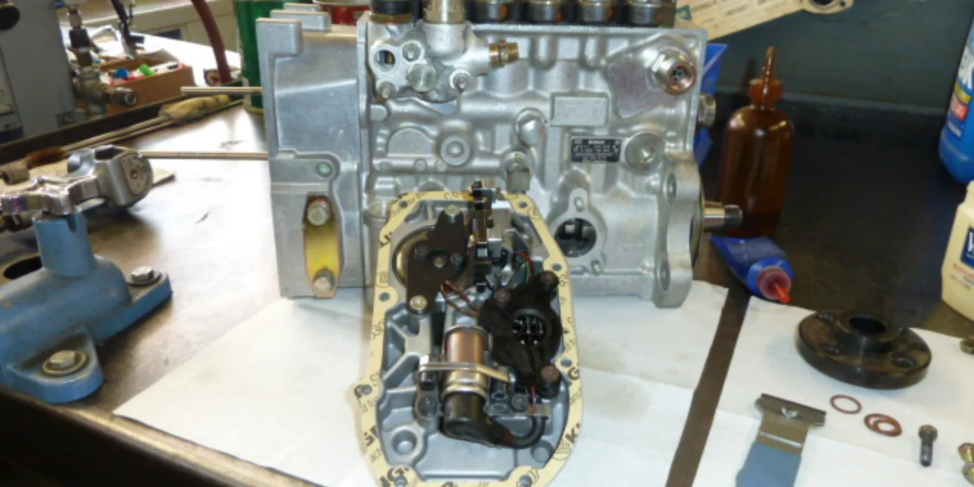
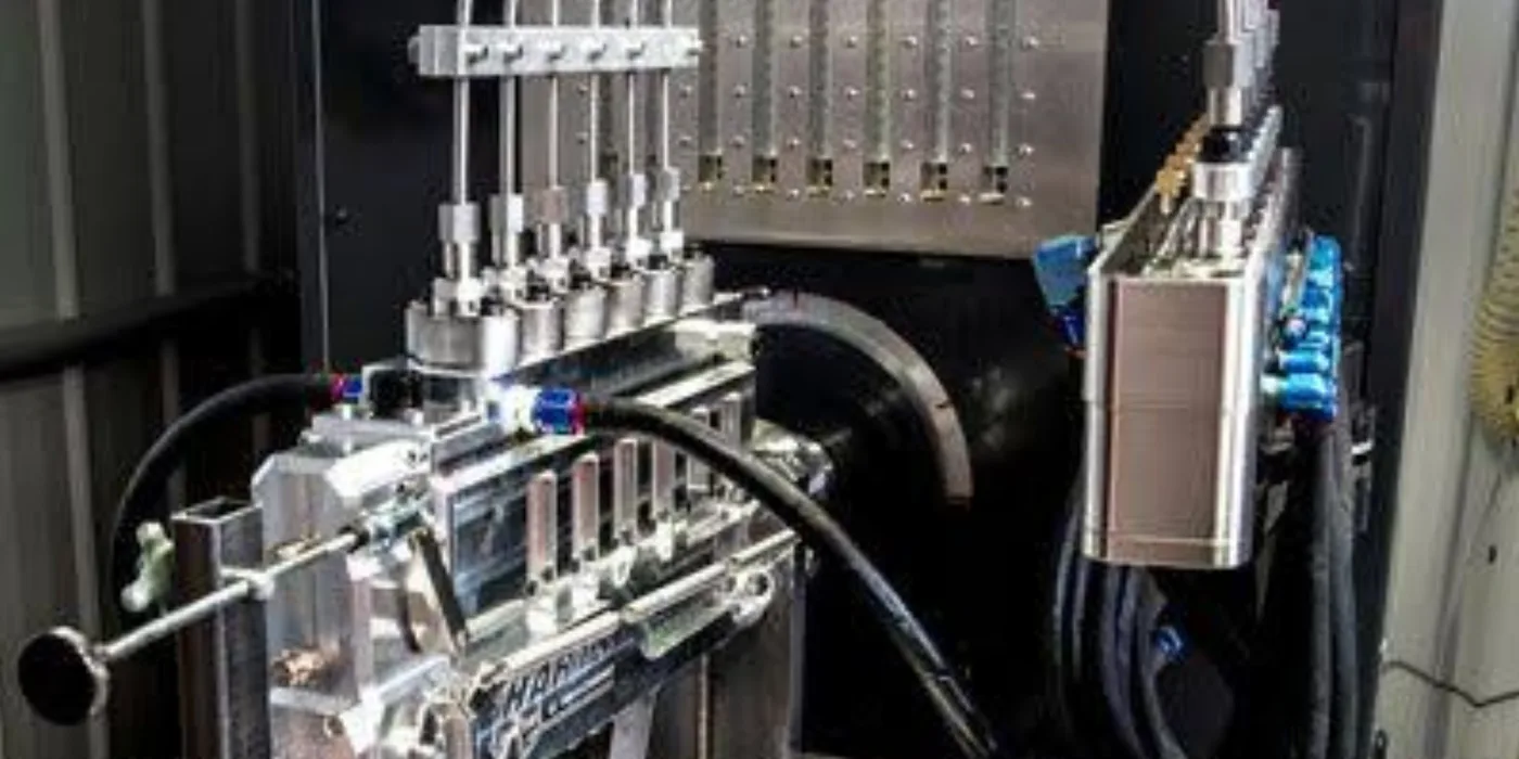
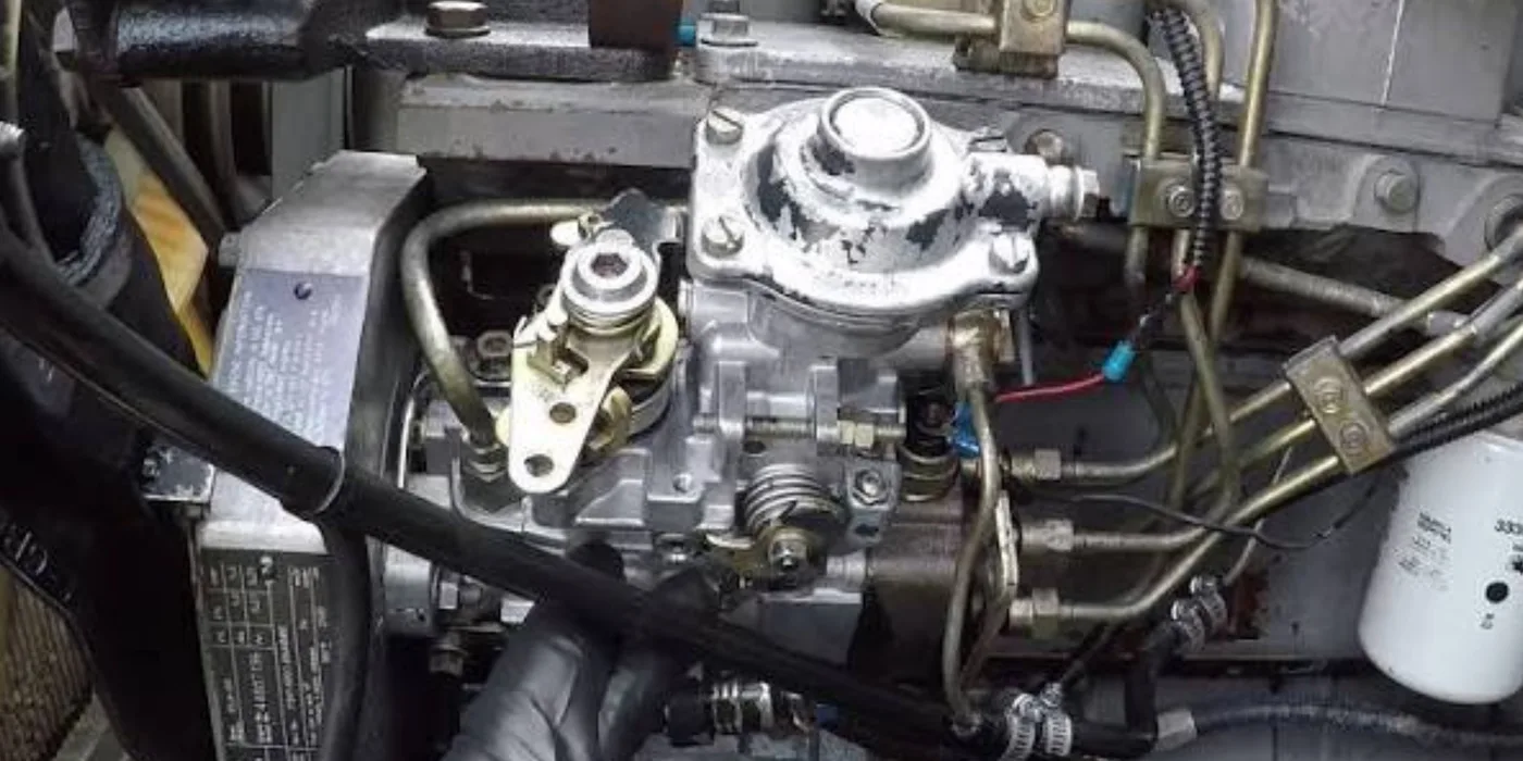
Diesel Injection Pump Repairs

Mechanical and electronic injection pumps meter and time fuel delivery. Faults here affect starting, power and consumption together, and pumps are normally reconditioned and calibrated rather than replaced outright.

What the work covers

  • •Inspection and fault diagnosis
  • •Governor and delivery assessment
  • •Seal and fuel-leak repair
  • •Reconditioning and calibration coordination
  • •Timing verification on refit
  • •Fuel supply and filtration check to prevent repeat failure

Symptoms we see

  • Hard starting
  • Weak power output
  • Hunting or surging
  • Excessive diesel consumption
  • Fuel leakage
  • Poor acceleration under load
Inline diesel injection pump removed from a generator engine for reconditioning at EmersonEIMS
Bosch inline injection pump on the rebuild bench with the governor cover removed, showing the internal governor mechanism and a new gasket
Injection pump internal components during inspection and reconditioning
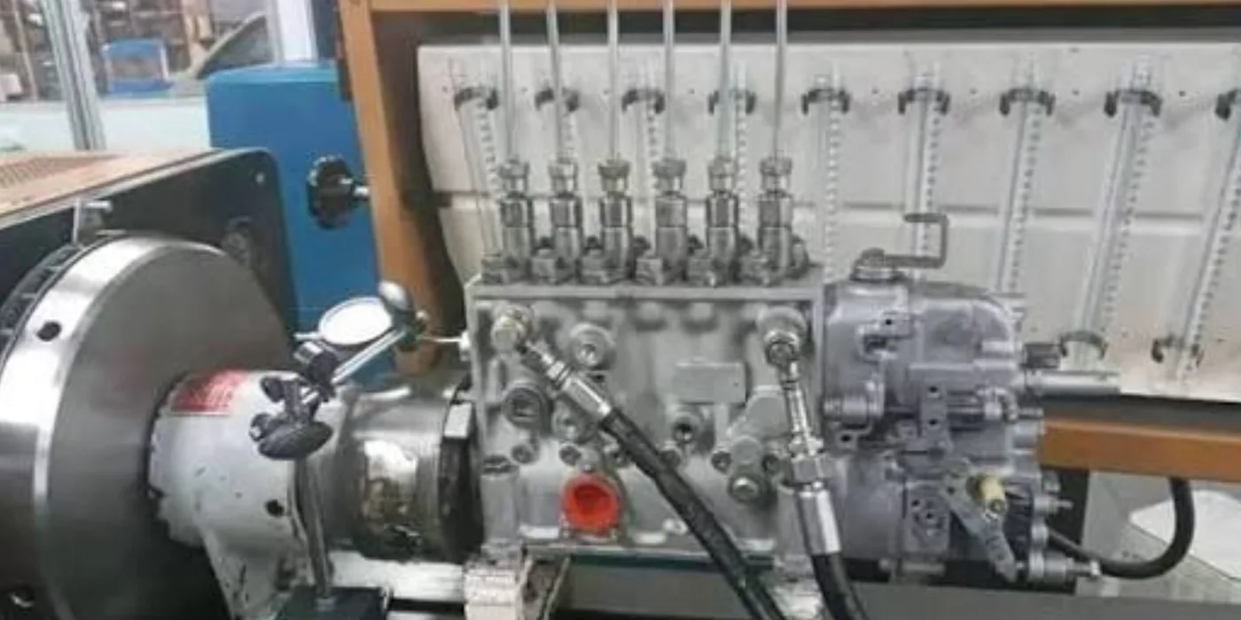
Diesel injection pump on the calibration bench with service tools

Understanding it

The injection pump is the heart of a mechanical diesel: it meters exactly the right quantity of fuel to each cylinder and delivers it at exactly the right instant, at very high pressure, through the governor that controls engine speed. It is a precision instrument built to fine tolerances. Faults here affect starting, power, smoke and fuel consumption together, and reconditioning is bench work requiring calibration, not a roadside swap.

Full technical guide — causes, repair, parts & prevention+
Why it fails — common causes
Dirty and watery fuel
The plunger-and-barrel elements are lapped to a few microns. Abrasive fuel wears them so delivery falls; water corrodes and seizes them. Fuel contamination is the dominant cause.
Wear in elements and delivery valves
Worn elements lose the pressure and volume needed, so the engine is down on power and smokes; worn delivery valves upset timing and cut-off.
Governor faults
Wear or sticking in the governor causes hunting, surging or an inability to hold speed under changing load.
Seized or sticking plungers
Corrosion from water or long standing seizes a plunger — the engine will not start or runs on fewer cylinders.
Seal and timing faults
Perished seals leak fuel; incorrect timing after careless refit gives hard starting and poor combustion.
How we repair it
  1. 1.Mount the pump on the test bench and record its as-received delivery and timing.
  2. 2.Dismantle in clean conditions; inspect elements, delivery valves, cam and governor.
  3. 3.Replace worn elements and delivery valves as matched sets; renew all seals and gaskets.
  4. 4.Reassemble and CALIBRATE on the bench — set delivery per cylinder, timing and governor response to the manufacturer's test data.
  5. 5.Confirm even delivery across all elements and correct cut-off before release.
How we test it before handover
  • ✓Calibrated bench test: delivery quantity per element across the speed range against the specification.
  • ✓Timing and phasing check between elements.
  • ✓Governor test for correct speed control and cut-off.
  • ✓On the engine: verify clean start, rated power and stable running after correct pump timing.
Parts & materials used
  • Plunger-and-barrel elements
  • Delivery valves and holders
  • Governor components
  • Seal and gasket kits
  • Drive and timing components
How to prevent it happening again
  • →Filtration and water separation are everything — the pump lives or dies by fuel cleanliness.
  • →Drain water separators and keep storage tanks free of water and rust.
  • →Do not let a set stand for long periods with untreated fuel; corrosion seizes elements.
  • →Have timing set correctly whenever the pump is refitted — guesswork here wastes fuel and power.
Request Injection-Pump Diagnosis

Turbocharger Inspection & Rebuild

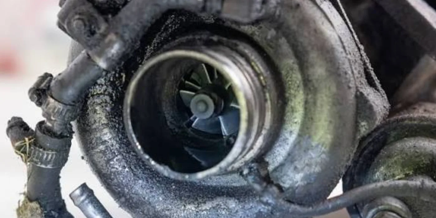
Turbochargers spin at very high speed on a thin oil film, so nearly every failure traces back to oil supply, oil condition or ingested debris. We look for the cause as well as the damage — replacing a turbo without finding the cause usually destroys the replacement.

What the work covers

  • •Shaft play, bearing and seal inspection
  • •Compressor and turbine wheel assessment
  • •Housing inspection for cracking and contact
  • •Carbon deposit cleaning
  • •Oil feed and drain line investigation
  • •Boost-loss and oil-carryover investigation
  • •Rebuild or replacement recommendation with reasons
  • •Balancing and testing where the equipment is available

Symptoms we see

  • Loss of power
  • Blue or black smoke
  • Whining or siren noise
  • Oil in the intake pipework
Turbocharger with the compressor housing exposed, showing the compressor wheel and carbon and oil deposits, during inspection at EmersonEIMS
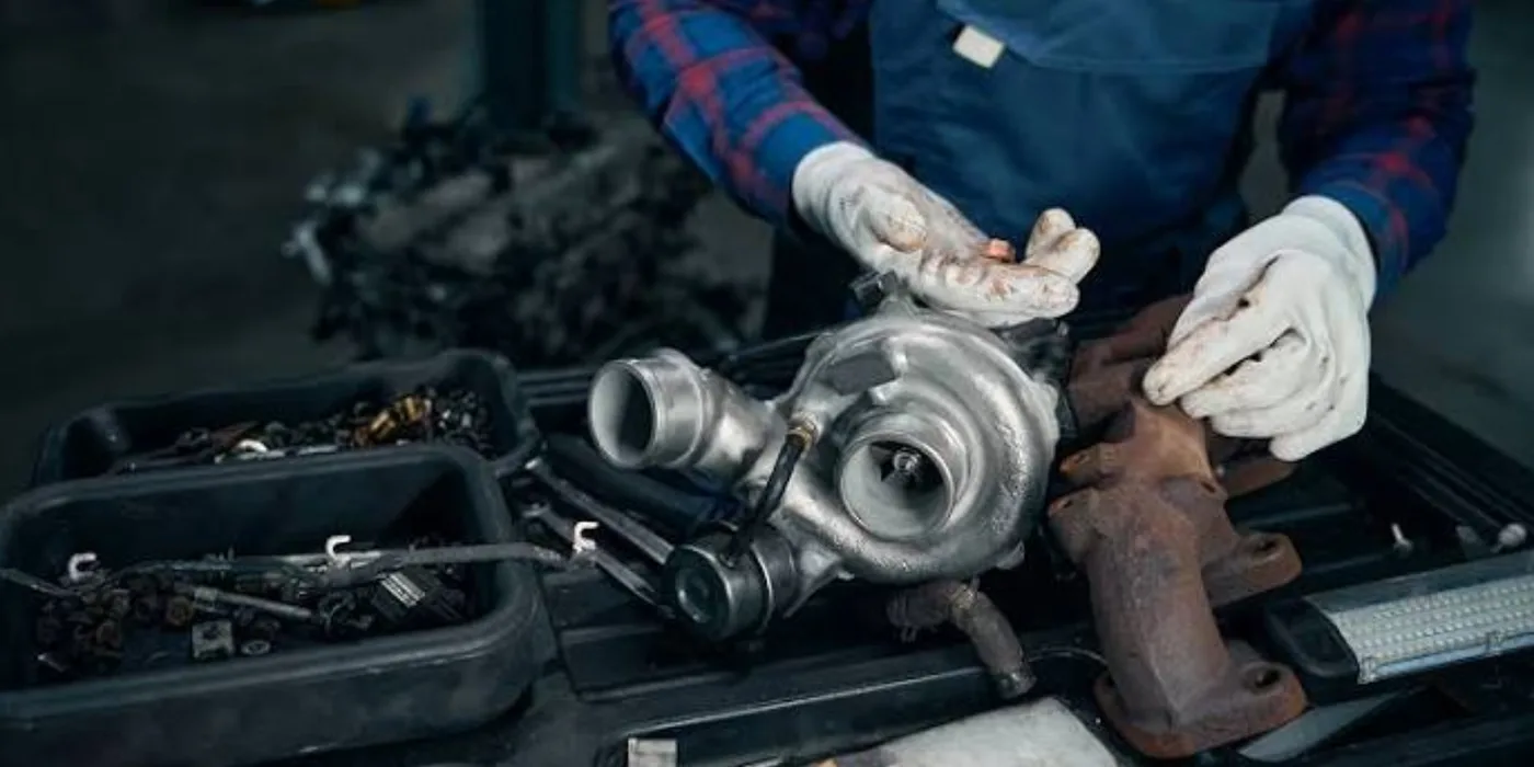
Turbocharger assessed for shaft play and wheel damage on the workshop bench
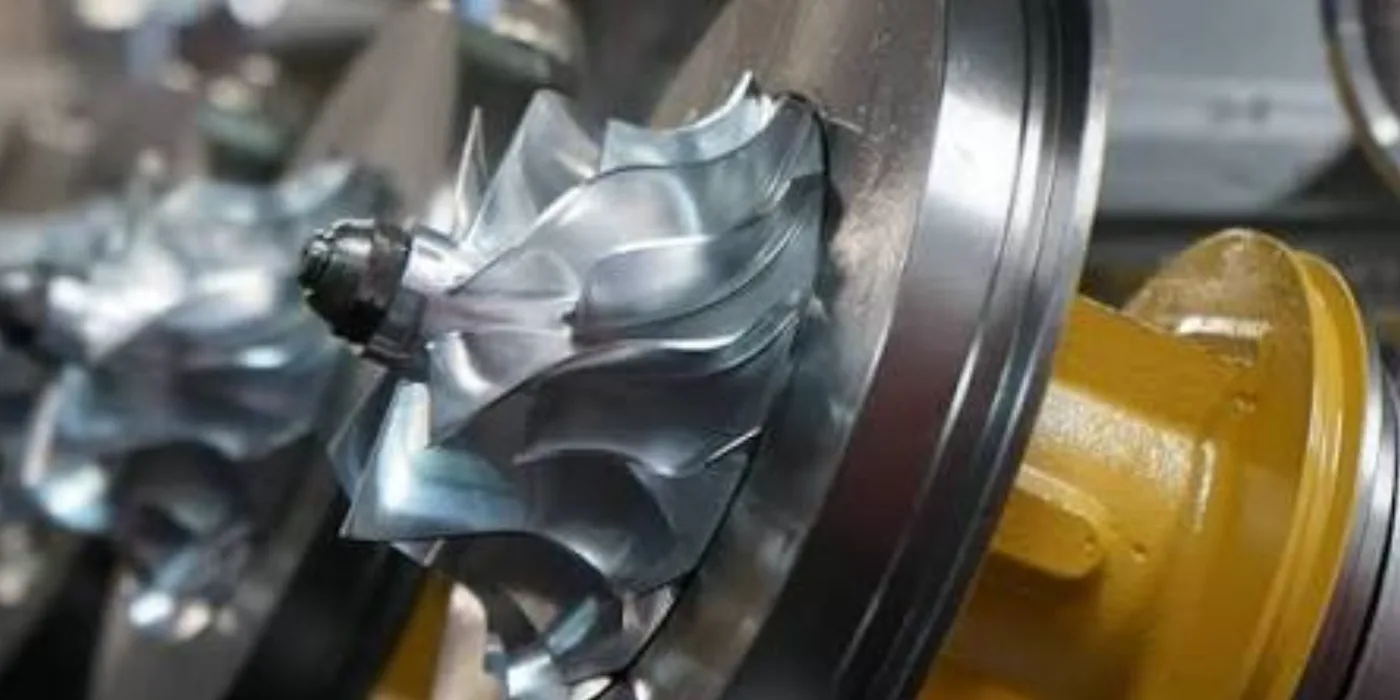
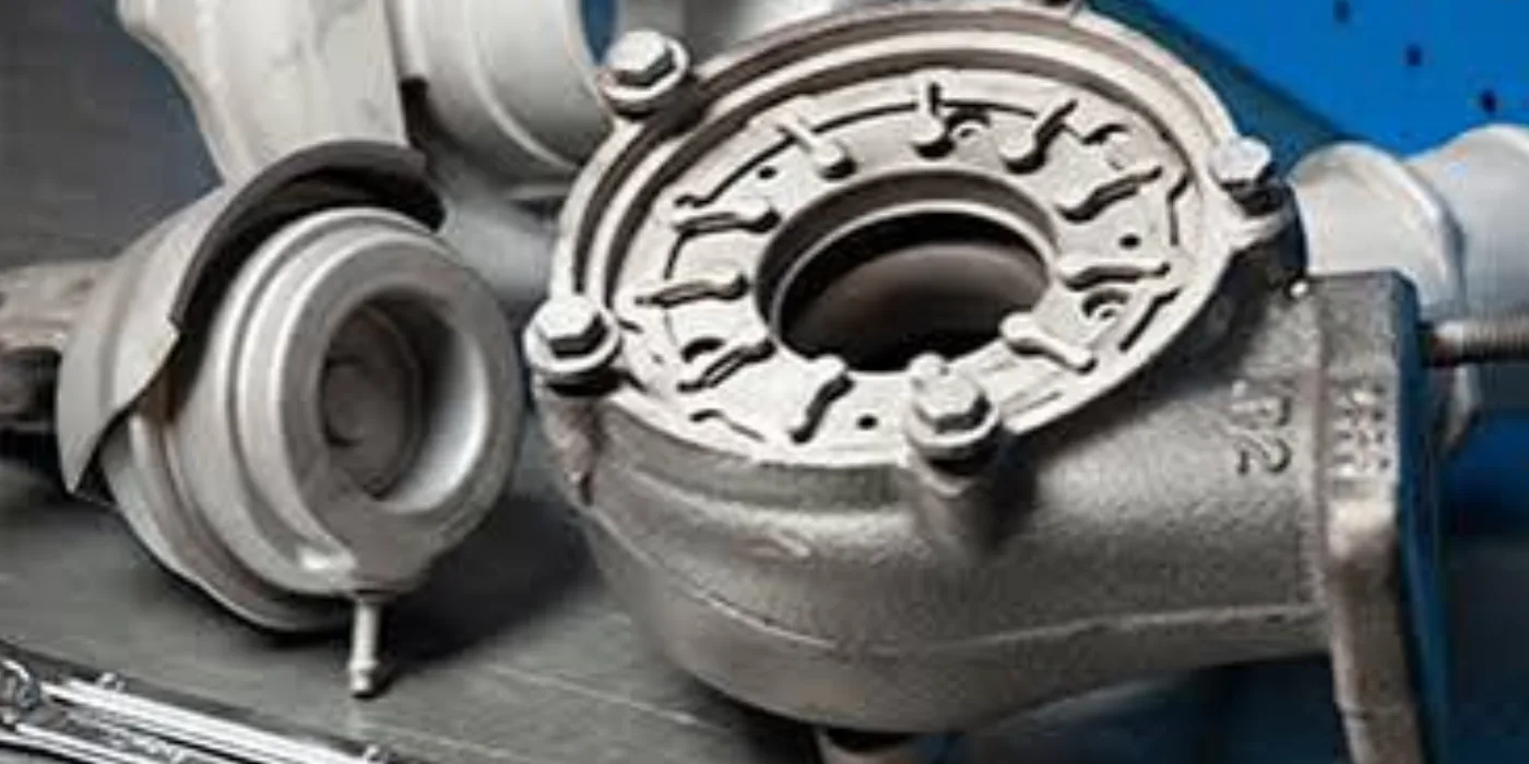
Turbocharger turbine and housing detail during teardown and inspection
Turbocharger components during rebuild at EmersonEIMS

Understanding it

A turbocharger uses the engine's own exhaust to spin a turbine, which drives a compressor that forces more air into the cylinders — more air means more fuel can be burnt, so more power. The shaft spins at tens of thousands of rpm on a thin film of engine oil. That is why almost every turbo failure traces back to oil supply, oil quality or something entering the wheels — not to the turbo itself. Fit a new turbo without finding the cause and it will fail again.

Full technical guide — causes, repair, parts & prevention+
Why it fails — common causes
Oil starvation
A restricted or delayed oil feed, or starting hard after standing, runs the bearings dry for the critical first seconds. The commonest killer.
Dirty or degraded oil
Contaminated or overdue oil scores the journal bearings and blocks the fine oil feed. Turbo life is oil life.
Foreign-object damage
A split intake hose or failed air filter lets grit strike the compressor wheel; a broken valve or carbon from upstream damages the turbine wheel.
Over-speeding and over-fuelling
A tuned-up pump, air leaks or altitude effects over-speed the turbo until the wheels burst or the bearings fail.
Blocked oil drain / seal failure
A restricted oil drain pressurises the centre housing and pushes oil past the seals into the intake or exhaust — seen as blue or white smoke and mistaken for engine wear.
How we repair it
  1. 1.Inspect for shaft radial and axial play, wheel damage and oil carry-over BEFORE condemning it.
  2. 2.Establish the CAUSE — check the oil feed and drain, the air filter and intake, and the fuelling — or the rebuild will fail.
  3. 3.Dismantle; assess compressor wheel, turbine wheel, shaft, bearings, seals and housings.
  4. 4.Rebuild with a bearing, seal and (where needed) CHRA kit, or fit a new/reconditioned unit where the wheels or housings are beyond use.
  5. 5.Balance the rotating assembly where the equipment is available; renew oil feed and drain lines.
How we test it before handover
  • ✓Check shaft free play and rotation for smoothness after rebuild.
  • ✓Balance verification of the rotating assembly where equipment allows.
  • ✓On the engine: prime the oil feed before first start; confirm boost, no smoke and no oil carry-over under load.
Parts & materials used
  • Turbo repair / CHRA kits (bearings, seals, thrust)
  • Compressor and turbine wheels where required
  • Oil feed and drain lines and gaskets
  • Complete new or reconditioned turbochargers
How to prevent it happening again
  • →Change engine oil and filters on schedule — the turbo depends on clean oil more than any other part.
  • →Let the engine idle briefly before shutdown after hard running, so the turbo cools with oil still flowing.
  • →Keep the air filter and all intake joints sealed — one split hose destroys a compressor wheel.
  • →Fix the root cause (oil feed, filtration, over-fuelling) at rebuild — a replacement turbo fitted to the same fault fails the same way.

Worth knowing: Not every damaged turbocharger is economically repairable. Where a rebuild is not sound engineering we will recommend a replacement instead.

Send Turbocharger Details

Complete Engine Overhauls

A full overhaul is a measured process, not a parts swap. The scope is set after dismantling and measurement, because what a worn engine actually needs is rarely what its symptoms first suggest.

What the work covers

  • •Initial diagnosis and compression assessment
  • •Dismantling and component measurement
  • •Cylinder head, valve and seat inspection
  • •Crankshaft, bearing and journal assessment
  • •Piston, ring and liner inspection
  • •Lubrication, cooling and fuel system assessment
  • •Gasket, seal and consumable replacement
  • •Reassembly to specified torques and clearances
  • •Static testing, controlled run-in and load testing where applicable

Symptoms we see

  • Blue smoke and high oil consumption
  • Low compression
  • Knocking under load
  • Metal in the oil or filter
  • Heavy crankcase blow-by
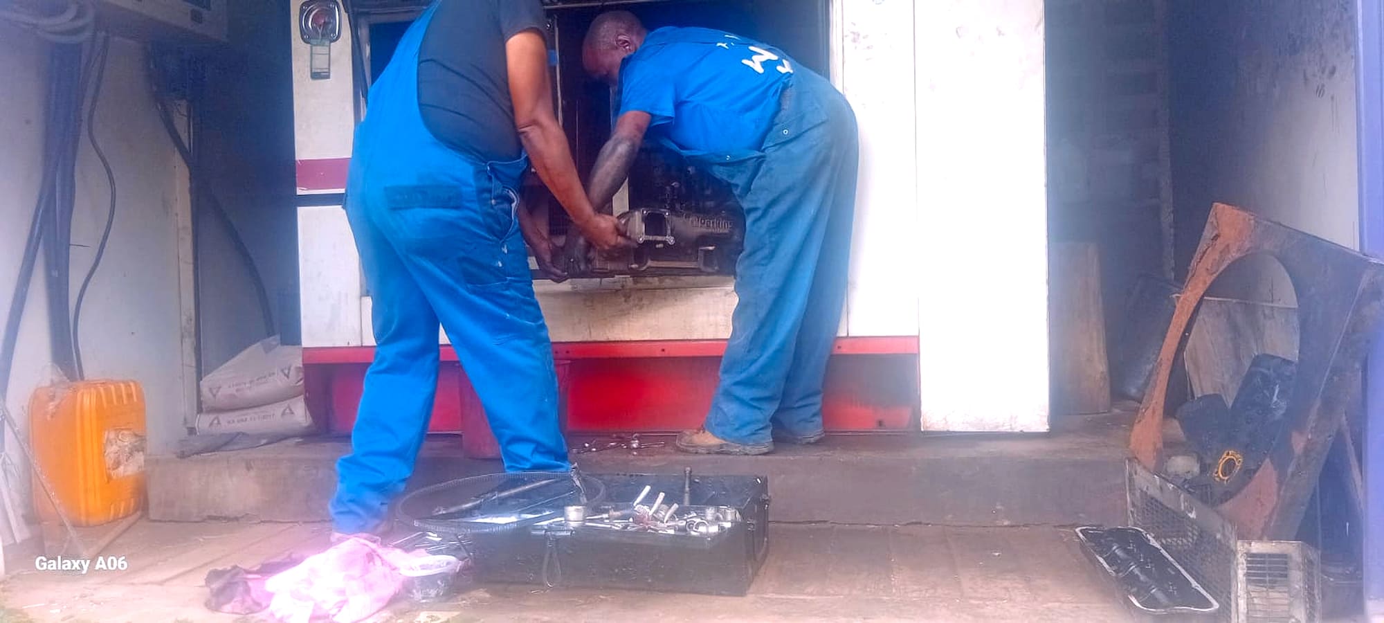
Two EmersonEIMS technicians overhauling the St Austin Academy 50 kVA Perkins generator engine on site, with the Perkins engine and an open tool kit visible
Technician fitting a new cylinder liner into a diesel generator engine block during an overhaul
Pistons seated in the bores of an inline diesel engine during overhaul and reassembly

Understanding it

An overhaul restores a worn diesel engine to serviceable condition by measuring every major component, renewing what is out of limit and rebuilding to specification. It is a measured process, not a parts swap: the scope is set only after the engine is stripped and measured, because what a worn engine actually needs is rarely what its symptoms first suggested. Done properly, an overhaul gives a tired set years of further reliable service for a fraction of replacement cost.

Full technical guide — causes, repair, parts & prevention+
Why it fails — common causes
High running hours and normal wear
Bores, rings, bearings and valve gear wear with hours. Eventually compression, oil control and oil pressure all fall together — the classic sign a full overhaul is due rather than another patch.
Overheating damage
A cooling failure warps heads, cracks liners and pistons and wipes bearings. Overheat damage is the commonest reason a mid-life engine needs opening up.
Oil starvation and contamination
Low oil pressure, missed oil changes or coolant/fuel in the oil destroy bearings and journals and score the bores.
Poor combustion and fuel faults
Worn injectors and pumps, and dirty fuel, wash bores and hole pistons — fuel-system faults left unfixed end as engine damage.
Neglected maintenance
Skipped filter and oil changes, dirty air and untreated coolant accelerate every wear mechanism at once.
How we repair it
  1. 1.Diagnose and measure before dismantling — compression and where possible cylinder-leakage tests to confirm the engine, not an ancillary, is at fault.
  2. 2.Strip the engine and measure every major component against the manufacturer's limits: bores/liners, crankshaft journals, bearings, pistons, valves and seats.
  3. 3.Recondition or renew to the measured need — rebore or renew liners, grind or renew the crankshaft to matched bearing sizes, renew pistons, rings, valves, guides and the full gasket set.
  4. 4.Assess and repair the lubrication, cooling and fuel systems at the same time, so a fixed engine is not returned to the fault that killed it.
  5. 5.Reassemble to the specified torques, clearances and timing — the difference between an overhaul that lasts and one that fails is in these numbers.
  6. 6.Static test, then controlled run-in, then load test where facilities allow, before handover.
How we test it before handover
  • ✓Compression and (where available) cylinder-leakage testing to confirm the diagnosis before work begins.
  • ✓Dimensional measurement of every reused component against the manufacturer's wear limits.
  • ✓Static checks on reassembly — oil pressure and no leaks on first prime and crank.
  • ✓Controlled run-in and, where facilities allow, load testing to prove power and stable running before release.
Parts & materials used
  • Pistons, rings and gudgeon pins
  • Cylinder liners / rebore to oversize
  • Main and big-end bearing shells (standard/undersize)
  • Crankshaft (reground or renewed) and thrust washers
  • Valves, guides, springs and seats
  • Full gasket and seal set
  • Oil and coolant service items
How to prevent it happening again
  • →Service on schedule — oil, filters, air and coolant. Most overhauls are premature and avoidable.
  • →Fix cooling and fuel faults immediately; both end as engine damage if ignored.
  • →Watch oil pressure and consumption as early warnings, and act before metal reaches the filter.
  • →Fix the root cause at overhaul — an engine rebuilt but returned to a cooling or fuel fault simply fails again.

Worth knowing: The exact scope and cost are confirmed only after dismantling and measurement. We quote the inspection first, then the work.

Request Engine Overhaul Assessment

Electrical, UPS, Motor & Pump Repairs

Rotating electrical machines and backup power systems, diagnosed before any repair is quoted.

Alternator & Electric Motor Rewinding

Rewinding covers three distinct machines that are often confused: the engine charging alternator, the generator end that produces your output, and industrial electric motors. We assess which of these has actually failed before quoting, because the remedy and the cost differ sharply.

What the work covers

  • •Single-phase, three-phase, pump, compressor and fan motors
  • •Generator alternator stator and rotor windings
  • •Insulation resistance testing before and after work
  • •Rewinding where it is technically and economically sound
  • •Bearing, shaft and terminal repair
  • •Rotor inspection and balance assessment
  • •No-load and output testing after rewind

Symptoms we see

  • No output voltage
  • Output collapses under load
  • Burning smell or discoloured windings
  • Motor trips its protection on start
  • Insulation failure after standing or flooding
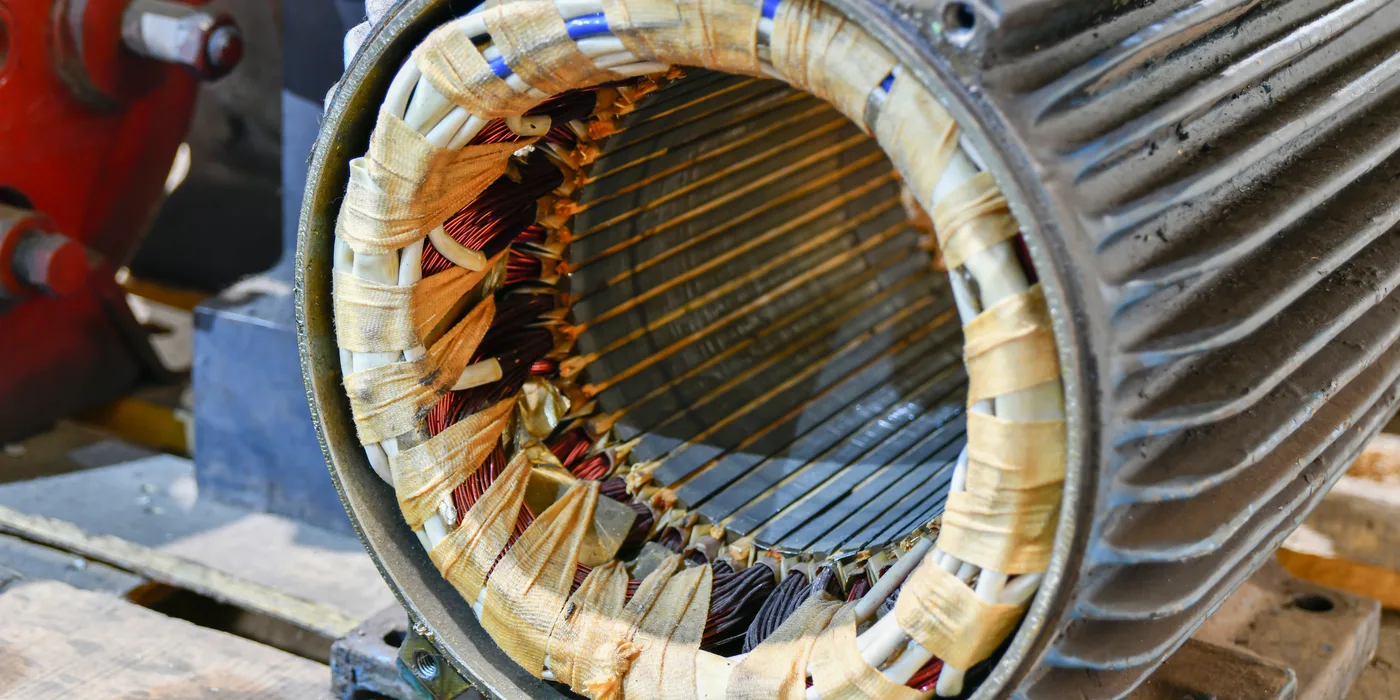
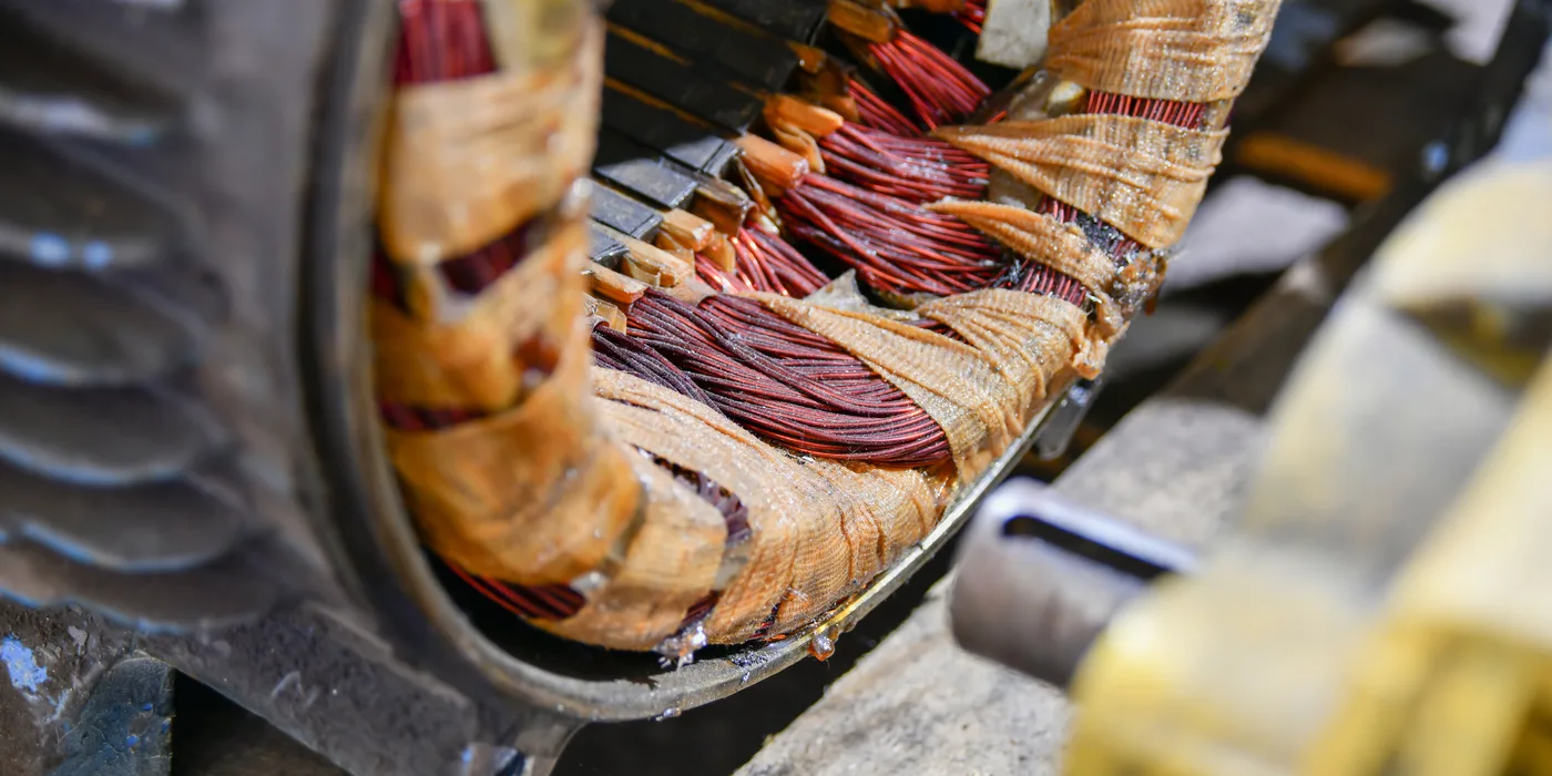
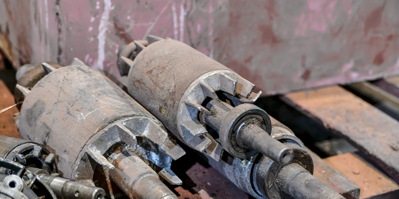
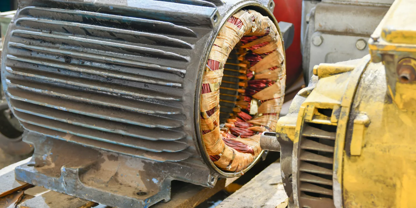
Three-phase stator freshly rewound with copper windings laced and taped, showing the core laminations and slot insulation
Electric motor stator winding during the rewinding process in the EmersonEIMS workshop
Rewound motor windings being laced and braced before varnish impregnation
Copper stator winding work on an industrial electric motor at EmersonEIMS

Understanding it

Rewinding replaces the copper windings in an electric motor or a generator alternator end. The winding is where electrical and magnetic energy meet, and it fails when its insulation fails — from heat, moisture, dirt or age. Rewinding is skilled work: the new winding must match the original turns, wire gauge, pitch and connection exactly, or the machine will run hot, draw wrong current, or not produce rated output.

Full technical guide — causes, repair, parts & prevention+
Why it fails — common causes
Insulation breakdown from heat
Every 10 °C of sustained overheating roughly halves insulation life. Overload, single-phasing, blocked ventilation and high ambient all cook the winding until it shorts turn-to-turn or to earth.
Moisture and contamination
Standby machines that sit idle absorb moisture; flooding, condensation and conductive dust all drop insulation resistance and cause earth faults — very common on coastal and highland sites without anti-condensation heaters.
Single-phasing and voltage imbalance
Losing one phase, or a large voltage imbalance, overheats the remaining windings rapidly and is a frequent killer of three-phase motors.
Bearing failure leading to winding damage
A collapsed bearing lets the rotor touch the stator; the rub destroys the winding in seconds. Many "burnt motors" started as a dry bearing.
Repeated starting and electrical stress
Frequent starts, stalls and switching surges stress the insulation and end-turns until they fail.
How we repair it
  1. 1.Test and record insulation resistance and winding resistance before stripping, to confirm the diagnosis.
  2. 2.Record the original winding data — turns, wire gauge, span, connection and lead arrangement — before removing anything.
  3. 3.Strip the old winding, clean the slots and inspect the core laminations for damage or shorting.
  4. 4.Re-insulate the slots and rewind to the recorded data with the correct wire and insulation class.
  5. 5.Connect, lace and brace the end-turns, then varnish-impregnate and cure to lock and seal the winding.
  6. 6.Fit new bearings and seals, reassemble, and check the airgap and rotor balance.
How we test it before handover
  • ✓Insulation-resistance (megger) test winding-to-earth and between phases.
  • ✓Winding-resistance test for balance across the three phases.
  • ✓Surge/comparison test where equipment is available, to prove turn-to-turn integrity.
  • ✓No-load run for current balance, temperature and vibration; output test on generator ends.
Parts & materials used
  • Enamelled copper winding wire (correct gauge)
  • Slot insulation, sleeving and lacing tape
  • Impregnating varnish
  • Bearings and shaft seals
  • Terminal blocks and lead wire
  • Anti-condensation heaters where fitted
How to prevent it happening again
  • →Fit and power the anti-condensation heaters on standby machines — they prevent the moisture that causes most winding failures.
  • →Protect against single-phasing and overload with correctly set protection.
  • →Keep the machine clean and ventilated; conductive dust and blocked cooling both cook windings.
  • →Renew bearings on condition, before they fail into the winding.
  • →Address the CAUSE at rewind time — a motor that burnt from single-phasing will burn again if the supply fault is not fixed.
Request Motor RepairView motor rewinding details →

UPS Repairs & Battery-System Diagnosis

A UPS that has never been load-tested is an assumption, not a backup. We diagnose the unit and the battery bank together, because a healthy UPS with a tired battery bank still fails at the moment it is needed.

What the work covers

  • •Fault diagnosis and alarm investigation
  • •Battery bank testing and replacement assessment
  • •Charger and inverter fault diagnosis
  • •Bypass and transfer problems
  • •Cooling fan and thermal fault investigation
  • •Internal connection and termination inspection
  • •Runtime assessment against actual connected load
  • •Preventive maintenance scheduling

Symptoms we see

  • UPS alarming or on permanent bypass
  • No runtime on mains failure
  • Batteries not holding charge
  • UPS overheating or fans noisy
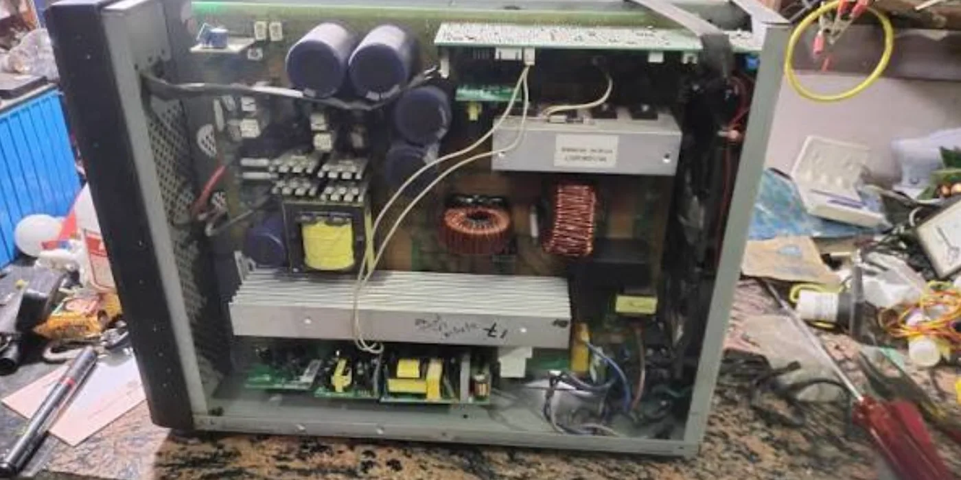
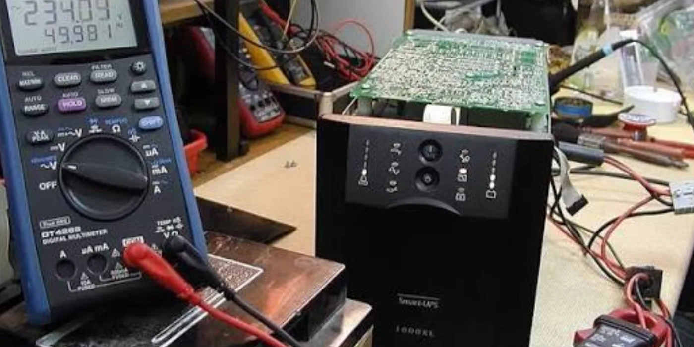
Online UPS opened on the bench showing DC-bus capacitors, power-stage heatsink, toroidal chokes and control boards during diagnosis at EmersonEIMS
UPS internal boards and components under inspection during repair
UPS power electronics assessed on the workshop bench
UPS internal wiring and components during fault diagnosis

Understanding it

A UPS bridges the gap between mains failing and the generator taking load, and cleans the power in between. It has three things that age: the batteries that store the energy, the power electronics that convert it, and the capacitors and fans that support them. A UPS that has never been load-tested is an assumption, not a backup — and the most common discovery is a healthy-looking UPS sitting on an exhausted battery bank.

Full technical guide — causes, repair, parts & prevention+
Why it fails — common causes
Battery bank ageing
Sealed lead-acid batteries lose capacity with heat and cycles; after a few years they hold minutes, not the rated runtime. The dominant cause of "UPS failed at the wrong moment".
Capacitor ageing
Electrolytic capacitors on the DC bus and boards dry out with heat and time, causing instability, alarms and eventual shutdown.
Fan failure and overheating
A stalled cooling fan lets the power stage overheat and derate or trip — a cheap part that takes out expensive ones.
Inverter / charger / power-stage faults
IGBT/MOSFET, driver or rectifier failures put the unit on permanent bypass or shut it down, often triggered by overload or a surge.
Bad connections and control faults
Loose battery links, corroded terminals and control-board faults produce misleading alarms and intermittent behaviour.
How we repair it
  1. 1.Diagnose the whole system — UPS AND battery bank together; test the batteries under load, not just their standing voltage.
  2. 2.Inspect the DC-bus and board capacitors, the power semiconductors, the charger and inverter stages, and the cooling fans.
  3. 3.Renew failed capacitors, fans and power devices; repair connections and terminations.
  4. 4.Replace battery blocks as a matched set where capacity has fallen — mixing old and new blocks shortens the whole bank.
  5. 5.Recalibrate/settle the unit and confirm clean transfer between mains, battery and bypass.
How we test it before handover
  • ✓Battery load / runtime test against the actual connected load.
  • ✓Transfer test — mains to battery to bypass and back — for clean, break-free switching.
  • ✓Output waveform and voltage checks under load.
  • ✓Thermal check that fans and the power stage hold temperature under sustained load.
Parts & materials used
  • Sealed lead-acid battery blocks (matched sets)
  • Electrolytic capacitors
  • Cooling fans
  • Power semiconductors and driver components
  • Fuses, connectors and battery links
How to prevent it happening again
  • →Load-test the UPS and battery bank periodically — the only honest proof it will hold when needed.
  • →Keep the UPS cool and ventilated; heat halves both battery and capacitor life.
  • →Replace the battery bank on age, before it fails — most banks need renewal every few years in Kenyan ambient.
  • →Do not overload the UPS; sustained overload stresses the power stage and cuts runtime.

Worth knowing: Repair viability and price can only be confirmed after diagnosis — some units and battery banks are past economic repair.

Request UPS DiagnosisOpen the UPS Intelligence Lab →

Pump Repairs & Overhauls

Borehole, booster and process pumps usually fail through seals, bearings or the driving motor rather than the pump body. Diagnosing which saves replacing a pump that is still serviceable.

What the work covers

  • •Borehole, surface, booster, centrifugal and drainage pumps
  • •Mechanical inspection and electrical testing
  • •Mechanical seal and bearing replacement
  • •Impeller and shaft inspection
  • •Motor rewinding where required
  • •Alignment assessment on coupled sets
  • •Control panel and protection diagnosis
  • •Performance testing after repair

Symptoms we see

  • Reduced flow or pressure
  • Pump tripping on overload
  • Leaking at the seal
  • Noise or vibration
  • Motor overheating
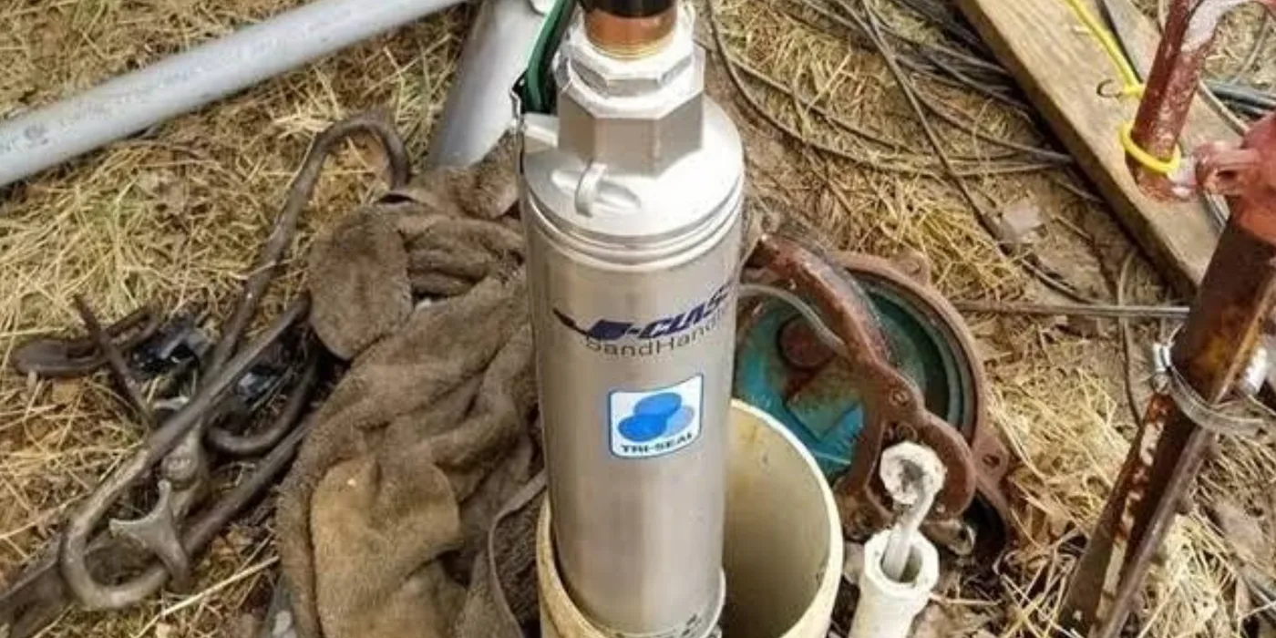
Stainless-steel submersible borehole pump at the wellhead during removal and inspection by EmersonEIMS
Pump assessed for seal, bearing and impeller condition during overhaul

Understanding it

Borehole, booster and process pumps move water or fluid, driven by an electric motor. They usually fail through the seals, bearings or the driving motor rather than the pump body, so diagnosing which saves replacing a pump that is still good. A submersible borehole pump works unseen down a well, which is why symptoms — falling flow, tripping, dry running — matter more than appearance.

Full technical guide — causes, repair, parts & prevention+
Why it fails — common causes
Mechanical seal failure
The seal that keeps water out of the motor wears or is damaged by dry running or abrasives; water then enters and destroys the motor.
Bearing wear
Worn bearings cause noise, vibration and eventually a rubbing, seizing rotor.
Impeller wear and blockage
Sand and grit erode the impellers and wear rings, dropping flow and pressure; debris blocks or jams the impeller.
Dry running
Running a pump with no water burns the seal and overheats the motor in minutes — a leading cause of borehole-pump failure when the water level drops.
Electrical and control faults
Motor winding failure, cable faults down the borehole, and control-panel/protection faults stop the pump or trip it repeatedly.
How we repair it
  1. 1.Withdraw and inspect the pump; test the motor windings and the down-hole cable for insulation and continuity.
  2. 2.Dismantle; assess seals, bearings, impellers, wear rings and shaft.
  3. 3.Renew mechanical seals and bearings; replace or skim worn impellers and wear rings; check shaft straightness.
  4. 4.Rewind or replace the motor where the winding has failed (see motor rewinding).
  5. 5.Check alignment on coupled surface sets and diagnose the control panel and protection.
How we test it before handover
  • ✓Insulation-resistance test of motor and cable before re-installation.
  • ✓Performance test for flow and pressure against the duty.
  • ✓Dry-run and overload protection check on the control panel.
  • ✓Confirm correct rotation and clean, vibration-free running.
Parts & materials used
  • Mechanical seals
  • Bearings
  • Impellers and wear rings
  • Shafts and sleeves
  • Motor winding materials (see rewinding)
  • Control and protection components
How to prevent it happening again
  • →Fit and set dry-run / low-level protection on borehole pumps — the single best defence against seal and motor loss.
  • →Match the pump to the borehole yield so it is not run dry as the water level draws down.
  • →Manage sand — worn wells and sandy water destroy impellers and seals quickly.
  • →Protect the motor with correctly rated overload and earth-fault protection, and keep the down-hole cable sound.
Request Pump InspectionView borehole & pump services →

Generator Fabrication & Fuel Systems

Canopies, exhausts, tanks, plinths and security — fabricated to the machine and the site, not to a standard drawing.

Generator Canopy Fabrication

A canopy has to do three things at once: reduce noise, keep weather out, and still let the machine breathe. Getting the airflow wrong turns a noise solution into an overheating problem, so canopies are designed around the specific set.

What the work covers

  • •Generator dimensions and cooling-air requirement
  • •Radiator discharge and air-path design
  • •Exhaust routing and heat separation
  • •Access doors for service and refuelling
  • •Sheet thickness and structural frame
  • •Acoustic lining selection
  • •Protective finish for the installation environment
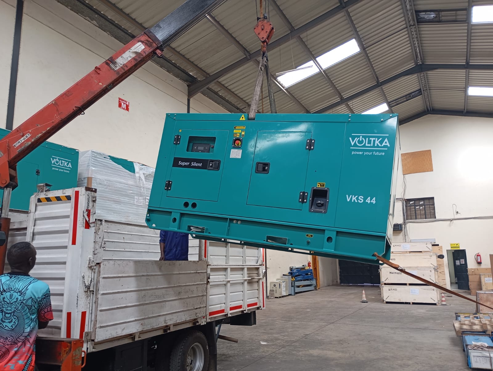
Canopied super-silent generator set lifted by crane inside the EmersonEIMS warehouse, showing the complete acoustic enclosure, access doors and control-panel cut-out
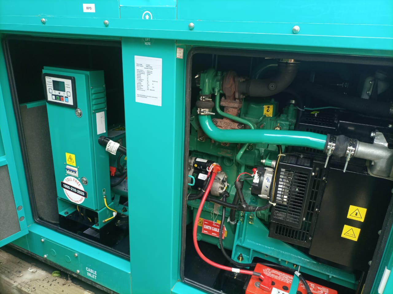
Canopied generator with the enclosure access doors open, showing the control panel, cable inlet and the engine bay inside the acoustic canopy

Understanding it

A generator canopy is a fabricated acoustic enclosure that does three jobs at once: reduce noise, keep weather out, and still let the machine breathe. Get the airflow wrong and a noise solution becomes an overheating problem, so a canopy is designed around the specific set — its cooling-air demand, its exhaust route and its service access — not bought as a standard box.

Full technical guide — causes, repair, parts & prevention+
Why it fails — common causes
Why sets need one
Noise complaints and by-law limits, weather and dust protection, security of the asset and its fuel, and a tidy, professional installation.
Where poor canopies fail
Undersized air paths cause the set to overheat under load; a badly routed exhaust cooks the enclosure; doors and panels that block service access mean maintenance is skipped.
How we repair it
  1. 1.Establish the set's cooling-air volume and radiator discharge requirement first — this governs the whole design.
  2. 2.Design the frame and panels in the correct sheet thickness with an air path that feeds the radiator and clears hot air.
  3. 3.Route the exhaust and separate its heat from the enclosure; provide access doors for service and refuelling.
  4. 4.Line acoustically to the noise objective and apply a protective finish for the installation environment.
  5. 5.Fabricate, fit and confirm the set runs at temperature on load inside the finished canopy.
How we test it before handover
  • ✓Run the enclosed set on load and confirm it holds operating temperature — airflow proven, not assumed.
  • ✓Check service access, door sealing and weather protection.
Parts & materials used
  • Steel frame and sheet panels
  • Acoustic lining
  • Louvres and attenuated air paths
  • Access doors, locks and hinges
  • Protective coating
How to prevent it happening again
  • →Never trade cooling airflow for noise reduction — a quiet set that overheats is a failed set.
  • →Keep louvres and air paths clear in service.
  • →Design in the exhaust route and service access from the start.

Worth knowing: We do not quote a decibel figure without acoustic design and measurement. Noise reduction is described in terms of the design approach, not a guaranteed number.

Request Canopy Design & Quote

Exhaust System Fabrication

An exhaust system carries hot gas safely away from people and plant. Done poorly it becomes a carbon-monoxide hazard and a source of back pressure that costs the engine power.

What the work covers

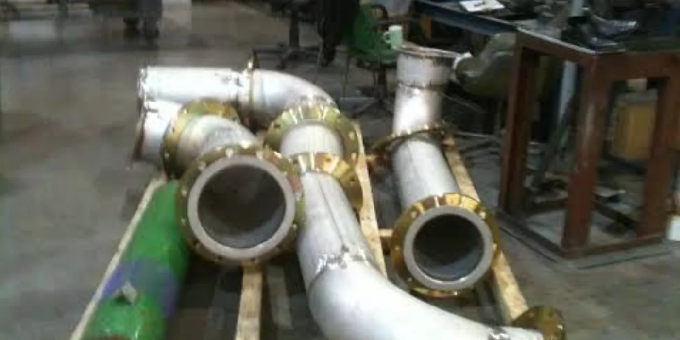
  • •Exhaust piping, bends and supports
  • •Flexible connections to isolate engine movement
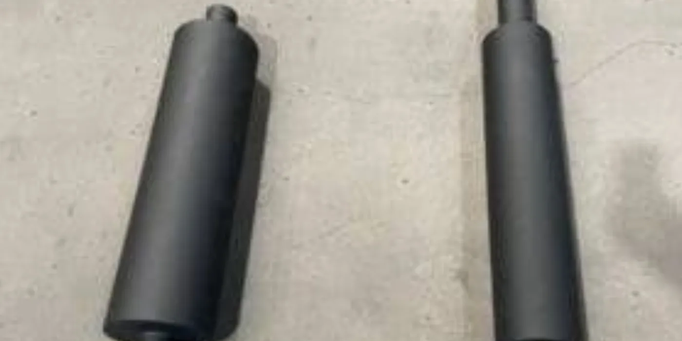
  • •Silencer selection and mounting
  • •Wall and roof penetrations
  • •Rain caps and safe discharge routing
  • •Thermal insulation and personnel guarding
  • •Back-pressure consideration in the routing design
Fabricated generator exhaust pipework with mandrel bends and newly welded flanges in the EmersonEIMS workshop
Two fabricated exhaust silencers manufactured for generator installations
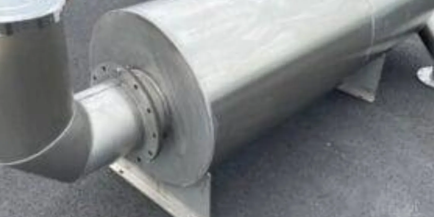
Large fabricated industrial exhaust silencer with flanged inlet and support feet

Understanding it

The exhaust system carries hot, toxic gas safely away from people and plant, and controls noise. Done poorly it is a carbon-monoxide hazard and a source of back-pressure that robs the engine of power. It is fabricated to the installation — pipe runs, silencer grade, flexible connections and safe discharge — not cut to a generic length.

Full technical guide — causes, repair, parts & prevention+
Why it fails — common causes
Why it is fabricated
Every plant room routes differently; the system must match the engine outlet, the building penetration and the safe discharge point, with the right silencer grade for the location.
Where exhausts fail
A missing flexible connection cracks the manifold; excessive back-pressure from undersized or blocked pipework loses power and overheats the engine; a leaking joint indoors is a CO danger.
How we repair it
  1. 1.Assess the plant room, engine outlet and required discharge point; select the silencer grade for the location (industrial, residential or critical).
  2. 2.Fabricate pipework and bends to suit, sized to keep back-pressure within the engine's limit.
  3. 3.Fit a flexible connection at the engine to isolate movement and protect the manifold.
  4. 4.Mount the silencer, form wall/roof penetrations, and route to a safe discharge clear of intakes and occupied areas.
  5. 5.Insulate or guard hot sections to protect personnel and reduce plant-room heat.
How we test it before handover
  • ✓Check for leaks along the finished run — no fumes may enter occupied space.
  • ✓Confirm back-pressure is within the engine manufacturer's limit where measurement is available.
  • ✓Verify safe, clear discharge and that hot surfaces are guarded.
Parts & materials used
  • Exhaust pipe, bends and supports
  • Flexible connections (bellows)
  • Silencers (industrial / residential / critical grade)
  • Flanges, gaskets and clamps
  • Thermal insulation and guarding
  • Rain caps and wall/roof penetration sleeves
How to prevent it happening again
  • →Always fit and maintain the flexible connection — its absence cracks manifolds.
  • →Keep the system sound and leak-free indoors; an exhaust leak in a plant room is a carbon-monoxide risk, not a nuisance.
  • →Do not add length or bends that raise back-pressure beyond the engine's limit.

Worth knowing: Exhaust routing must account for heat, fumes, back pressure, nearby occupants and combustible materials. We assess the plant room, not just the pipe run.

Request Exhaust-System Assessment

Diesel Fuel Storage Tanks

Fuel storage determines how long a set runs unattended, and it is the part of an installation most often changed after commissioning. It is also where fire and environmental requirements apply most directly.
What the work covers

  • •Bulk, day and base tanks
  • •Bunded containment arrangements
  • •Tank supports and structural frames
  • •Fill, vent, suction and return connections
  • •Drain and inspection points
  • •Level indication provisions
  • •Protective coating for the installation environment
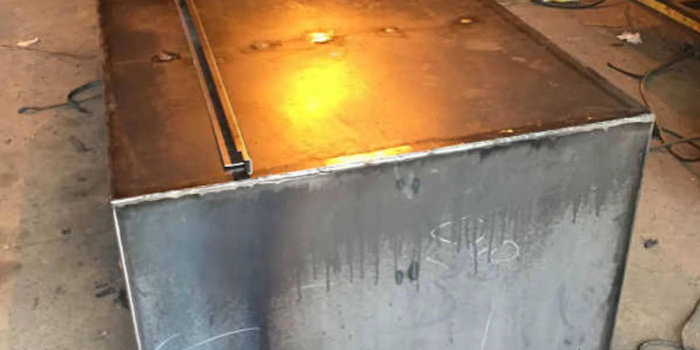
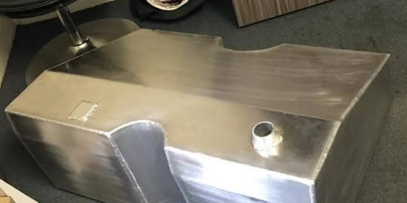
Fabricated rectangular steel diesel fuel tank under construction with welded seams in the EmersonEIMS workshop
Diesel fuel storage tank fabrication showing welded steel plate construction
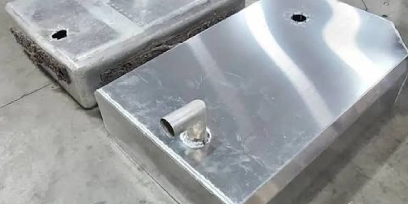
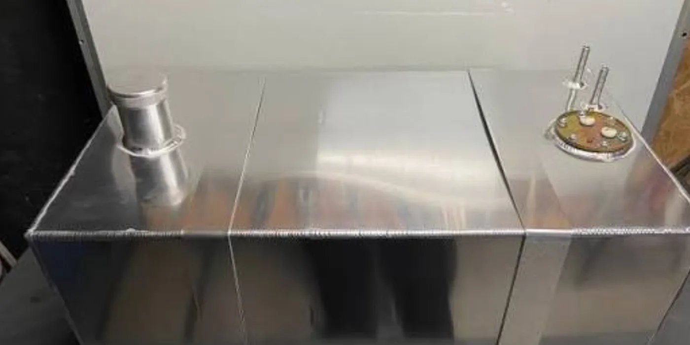
Fuel tank fabrication with connections and supports being formed
Completed fabricated diesel fuel tank for a generator installation

Understanding it

Fuel storage decides how long a set runs unattended and, with automation, how reliably it is kept fed. Tanks are fabricated to the site — capacity, bulk-and-day-tank arrangement, containment and connections — and this is where fire and environmental requirements apply most directly. Poor tank work causes the two commonest diesel problems: a day tank that runs dry and a bulk tank nobody noticed was empty.
Full technical guide — causes, repair, parts & prevention+
Why it fails — common causes
Why tanks are fabricated to order
Runtime target, footprint, bulk-vs-day arrangement and containment all vary by site; a tank must be built for the actual installation and its compliance needs.
Where fuel systems fail
Water and rust in neglected tanks ruin injectors and pumps; a day tank with no automatic fill starves the engine; no containment turns a leak into an environmental incident.
How we repair it
  1. 1.Confirm capacity, material, structural support and containment against the site and its compliance requirements.
  2. 2.Fabricate the tank (base, day or bulk) with proper support and, where required, a bund.
  3. 3.Form fill, vent, suction, return, drain and inspection connections; add level indication.
  4. 4.Apply protective coating for the environment; pressure/leak-check before commissioning.
  5. 5.Where automation is required, integrate transfer, level control and monitoring (see fuel automation).
How we test it before handover
  • ✓Leak / pressure test of the fabricated tank before installation.
  • ✓Function-check fill, vent, suction and return, and level indication.
  • ✓Confirm containment and safe filling arrangements.
Parts & materials used
  • Steel plate and sections
  • Bund / containment fabrication
  • Fill, vent, suction, return and drain fittings
  • Level gauges and senders
  • Protective coating
  • Tank supports and frames
How to prevent it happening again
  • →Keep tanks free of water — drain and inspect; water is the enemy of injectors and pumps.
  • →Maintain the day-tank fill and level controls so the engine is never starved.
  • →Provide and maintain containment where required, for compliance and to contain leaks.

Worth knowing: Capacity, material, structural support, containment and ventilation are assessed against the site before fabrication begins.

Request Fuel-Tank Quotation

Fuel-Tank Automation & Monitoring

Automating fuel transfer removes the two most common diesel problems on a standby installation: a day tank that runs dry, and a bulk tank nobody notices is empty until the set stops.

What the work covers

  • •Level monitoring with high and low alarms
  • •Automatic transfer from bulk to day tank
  • •Transfer pump start/stop control with manual override
  • •Overflow protection
  • •Bund or leak alarm where specified
  • •Consumption monitoring for the generator
  • •Control panel indication
  • •Remote alerts by GSM or network where available
  • •Event and alarm history

Understanding it

Fuel automation removes the two most common diesel failures on a standby installation: a day tank that runs dry and a bulk tank nobody realised was empty. It adds level monitoring, automatic transfer from bulk to day tank, alarms and, where specified, remote alerts — so the fuel side looks after itself and warns before it becomes a problem.

Full technical guide — causes, repair, parts & prevention+
Why it fails — common causes
Why sites add it
Manual fuel management fails when nobody is watching — which is exactly when a standby set is needed. Automation makes the fuel side self-managing and auditable.
What it prevents
Engine starvation from an empty day tank, unnoticed bulk depletion, overfills and spills, and undetected fuel loss.
How we repair it
  1. 1.Establish the tanks, levels and functions required for the specific installation.
  2. 2.Install level sensing with high and low alarms on the relevant tanks.
  3. 3.Set up automatic bulk-to-day transfer with pump start/stop control and manual override.
  4. 4.Add overflow protection and, where specified, bund/leak alarms and consumption monitoring.
  5. 5.Provide panel indication and, where required, GSM or network remote alerts and event history.
How we test it before handover
  • ✓Function-test automatic transfer, high/low alarms and manual override.
  • ✓Confirm overflow protection operates and remote alerts (where fitted) are received.
Parts & materials used
  • Level sensors and float assemblies
  • Transfer pumps and controls
  • Alarm and indication panel
  • Overflow and bund-alarm devices
  • GSM / network alert modules where specified
How to prevent it happening again
  • →Advertise and supply only the monitoring functions specified for the project — the scope above is the menu, not a standard package.
  • →Test the automation periodically so it is proven before it is relied on.

Worth knowing: Only the monitoring functions specified and supplied for your project are provided — the list above is the available scope, not a standard package.

Discuss Fuel AutomationView diesel automation →

Generator Plinths & Foundations

The plinth carries the machine, controls its vibration and keeps it clear of water. It is designed from the actual generator weight and footprint and the actual ground conditions.

What the work covers

  • •Site measurement and ground assessment
  • •Generator weight and footprint confirmation
  • •Reinforced concrete base design and construction
  • •Anchoring and anti-vibration mounting provisions
  • •Drainage and water clearance
  • •Cable and conduit entry provisions
  • •Access clearance for service and refuelling
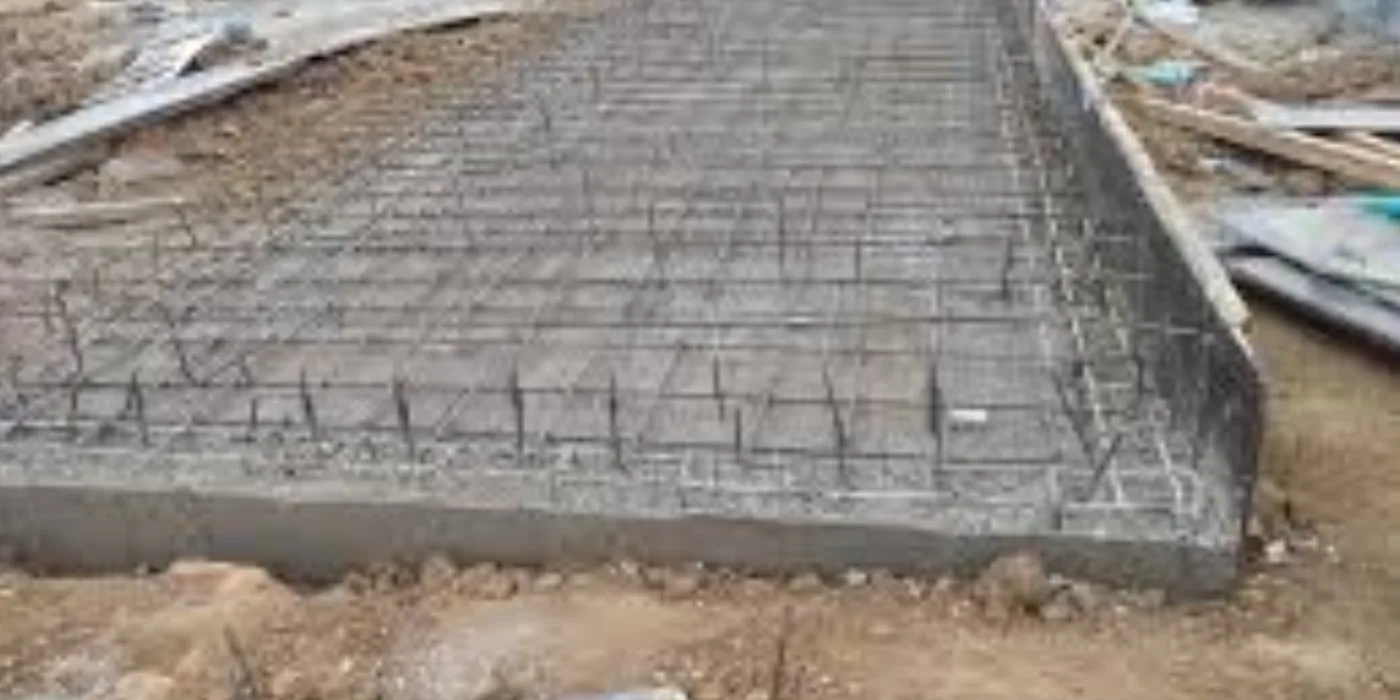
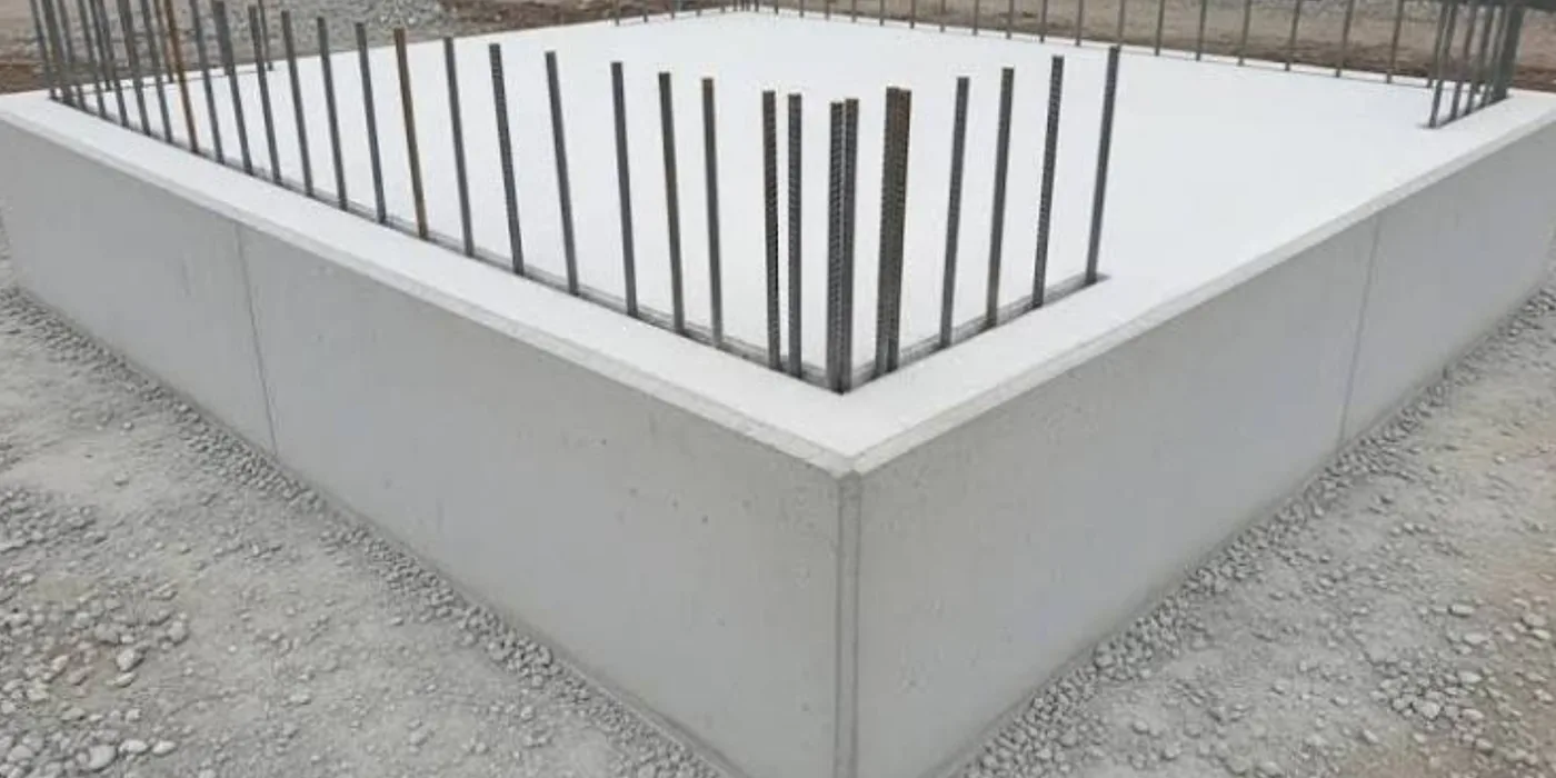
Freshly cast reinforced concrete generator plinth showing the embedded steel reinforcement grid and formed edges
Reinforced concrete generator foundation base constructed by EmersonEIMS on site

Understanding it

A generator plinth is the reinforced concrete base the machine sits on. It carries the weight, controls vibration transmitted into the building, and keeps the set clear of water. It is designed from the actual generator weight and footprint and the actual ground conditions — there is no universal size, and a plinth quoted from a photograph is guesswork.

Full technical guide — causes, repair, parts & prevention+
Why it fails — common causes
What the plinth must do
Support the static and dynamic load without settling, anchor the set, isolate vibration through anti-vibration mounts, drain water away and give safe working clearance around the machine.
Where poor foundations fail
An undersized or poorly reinforced base cracks and settles; no drainage lets water pool under the set; missing anchor and AV provisions transmit vibration into the structure.
How we repair it
  1. 1.Measure the site and confirm the generator weight and footprint and the ground conditions.
  2. 2.Design the reinforced concrete base to carry the static and dynamic load.
  3. 3.Set out anchor points and anti-vibration mounting provisions, cable-entry provisions and drainage.
  4. 4.Form, reinforce and cast the base with correct reinforcement and cover.
  5. 5.Cure and confirm level, anchor positions and clearance before the set is placed.
How we test it before handover
  • ✓Confirm the cured base is level, correctly dimensioned and cured before loading.
  • ✓Verify anchor and AV-mount positions match the set.
Parts & materials used
  • Reinforcement steel (rebar / mesh)
  • Concrete to the design mix
  • Anchor bolts and AV-mount provisions
  • Cable-entry and drainage provisions
How to prevent it happening again
  • →Design every plinth for the specific set and ground — never reuse a generic size.
  • →Provide drainage so water never stands under the machine.
  • →Fit the anti-vibration mounts the plinth was designed for; they protect both set and building.

Worth knowing: There is no universal plinth size. Every foundation is designed for the specific set and site — we will not quote one from a photograph.

Request Plinth Assessment

Generator Security Cages

Outdoor generators and their fuel systems are theft targets. A cage protects the asset without becoming a new problem — provided it does not choke the machine.

What the work covers

  • •Welded steel construction to suit the site
  • •Lockable access doors
  • •Ventilation allowance sized to the cooling requirement
  • •Maintenance and refuelling access
  • •Weather-resistant finish
  • •Anchoring and anti-tamper detailing
  • •Provision for fuel and electrical connections
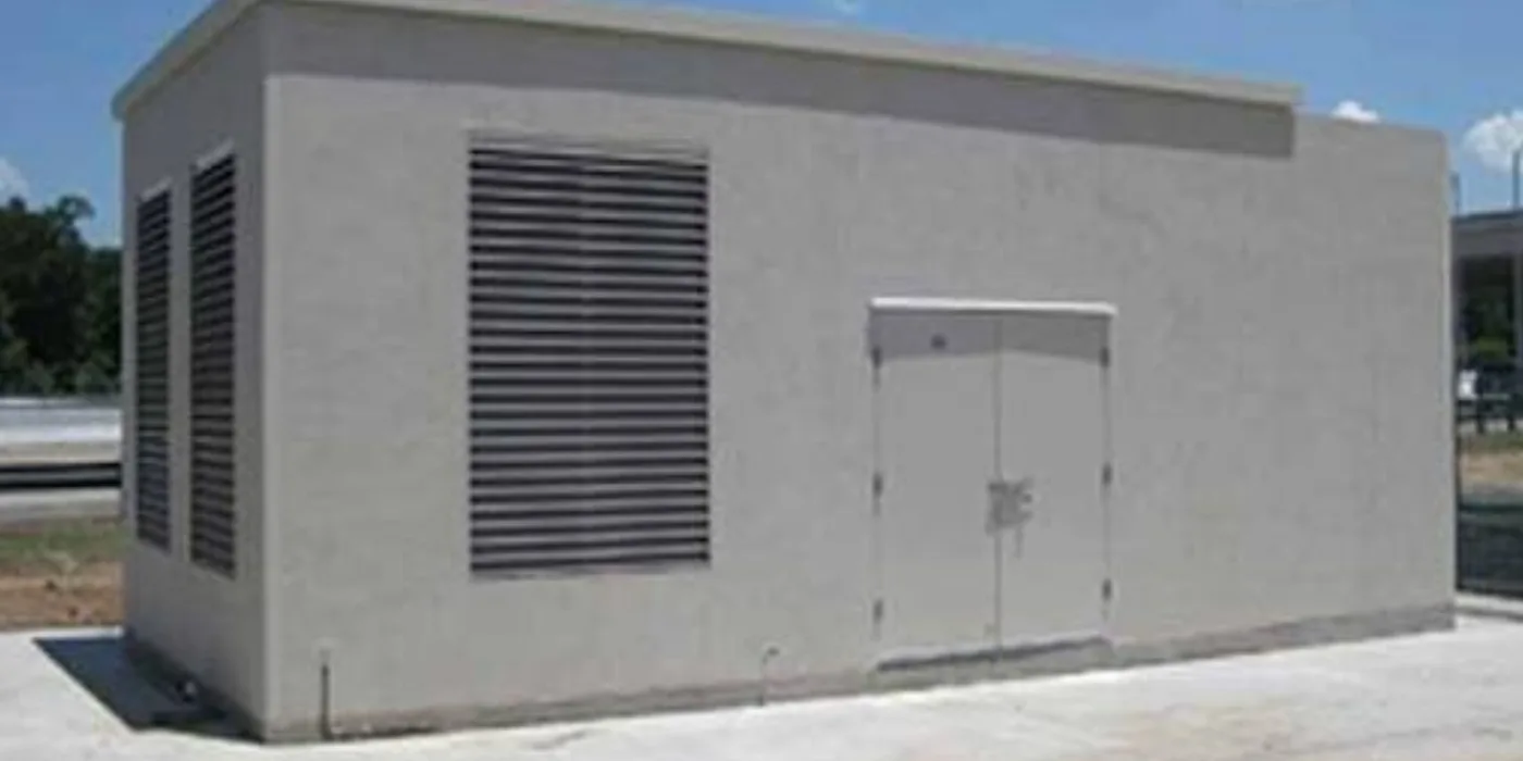
Completed masonry generator house with large louvre ventilation panels and secure steel double doors
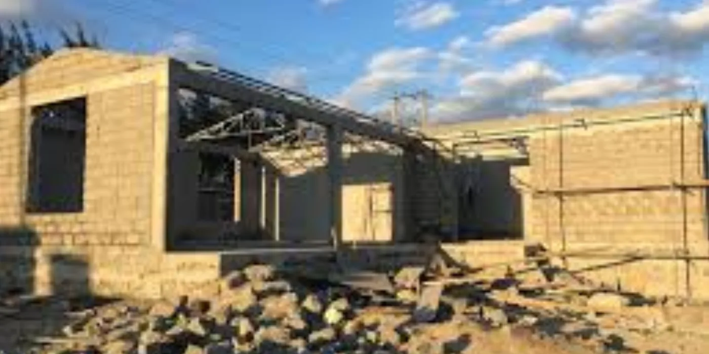
Masonry generator house under construction with ventilation-block walls and reinforced concrete columns
Generator enclosure construction showing ventilation openings and secure structure

Understanding it

Outdoor generators and their fuel systems are theft and tamper targets, and often need weather protection beyond a canopy. EmersonEIMS builds both welded steel security cages and full masonry generator houses — walk-in enclosures with louvred ventilation and secure doors. Either way the rule is the same: protect the asset without choking the machine.

Full technical guide — causes, repair, parts & prevention+
Why it fails — common causes
Why sites need enclosure
Security of the generator, batteries and fuel; weather protection; noise containment; and a safe, controlled space for maintenance.
The critical constraint
The enclosure must never obstruct radiator airflow, exhaust discharge or maintenance access. Ventilation is sized to the cooling requirement — a secure box that overheats the set has failed.
How we repair it
  1. 1.Establish the set's ventilation requirement and access needs first — these govern the design.
  2. 2.For a steel cage: fabricate welded steel construction with lockable access doors and ventilation sized to the cooling requirement.
  3. 3.For a generator house: build masonry walls with louvred ventilation openings, reinforced columns, and secure steel doors.
  4. 4.Provide maintenance and refuelling access and provision for fuel and electrical connections.
  5. 5.Finish for the environment; confirm the set runs at temperature inside the finished enclosure.
How we test it before handover
  • ✓Run the enclosed set on load and confirm it holds operating temperature — ventilation proven.
  • ✓Check secure locking, weather protection and full service access.
Parts & materials used
  • Welded steel sections and mesh (cages)
  • Masonry, reinforced columns and louvre blocks (houses)
  • Secure steel doors, locks and hinges
  • Ventilation louvres sized to the cooling load
  • Protective finish
How to prevent it happening again
  • →Size ventilation to the cooling requirement, never below it — security must not cost airflow.
  • →Keep louvres and vents clear in service.
  • →Preserve full maintenance and refuelling access in the design.

Worth knowing: A cage must never obstruct radiator airflow, exhaust discharge or maintenance access — that is designed in, not worked around afterwards.

Request Security-Cage Quote

Industrial Machinery Fabrication

Processing machinery built to a defined duty, material and output rather than copied from a photograph.

Hammer Mill Fabrication & Repairs

Hammer mills are specified from what they must process and what output is required. The same frame with the wrong screen, hammer or motor gives the wrong product at the wrong rate.

What the work covers

  • •Frame and grinding chamber fabrication
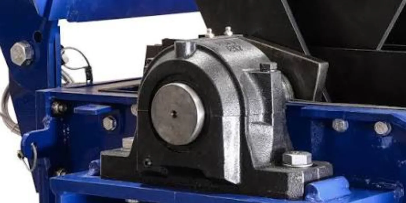
  • •Rotor assessment and hammer replacement
  • •Screen selection for the required output size
  • •Bearings, bearing housings and shaft repair
  • •Belt, pulley and drive arrangement
  • •Motor mounting and alignment
  • •Feed hopper and discharge arrangement
  • •Safety guarding
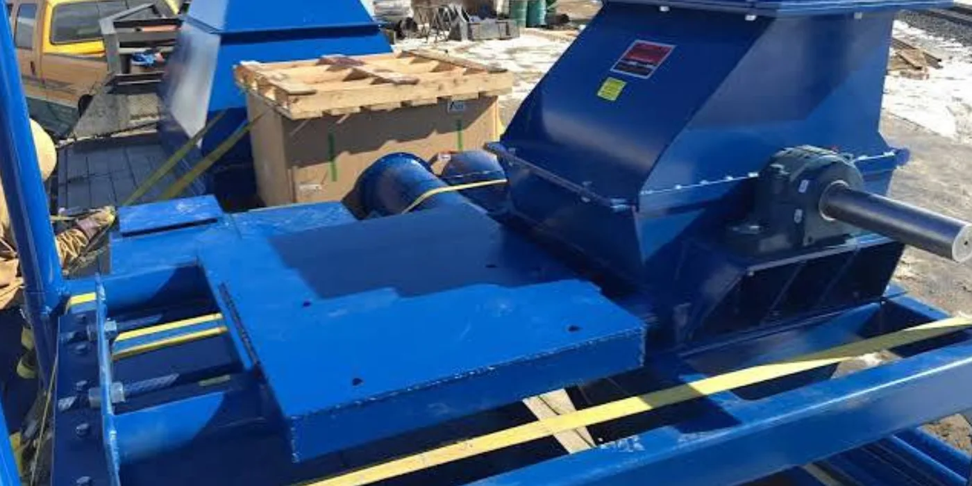
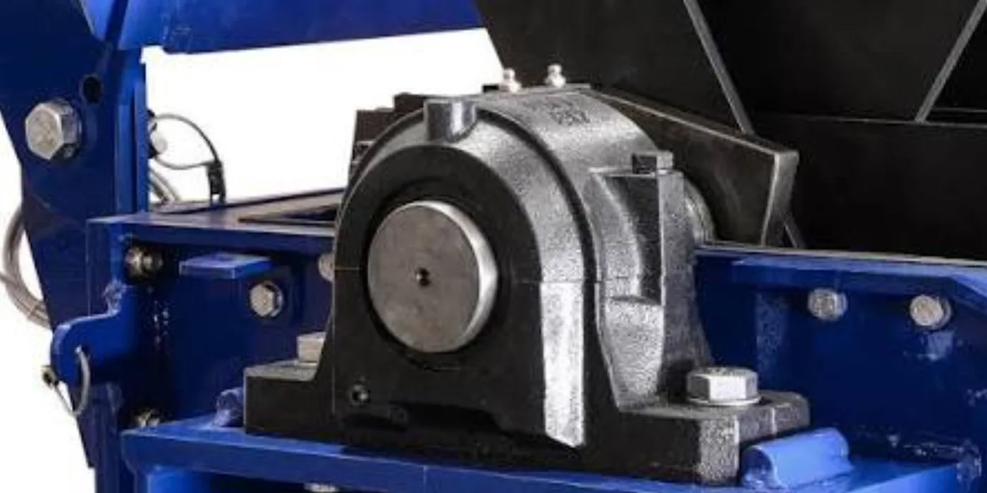
Fabricated industrial hammer mill with feed hopper and gearbox drive, mounted on a steel frame
Hammer mill construction showing the grinding chamber and drive arrangement
Industrial hammer mill fabrication in progress at EmersonEIMS
Fabricated hammer mill and its drive and framing

Understanding it

A hammer mill reduces material — grain, minerals, agricultural or industrial feedstock — by beating it with swinging hammers against a screen inside a grinding chamber. Output size is set by the screen; capacity by the rotor, hammers and drive power. EmersonEIMS fabricates, repairs and rebuilds hammer mills to a defined duty, because the same frame with the wrong screen, hammer or motor gives the wrong product at the wrong rate.

Full technical guide — causes, repair, parts & prevention+
Why it fails — common causes
What determines the design
The material being processed, the required output size, the expected capacity, the motor power available, the duty cycle and the feeding method — all of these set the specification.
Where hammer mills wear
Hammers and screens are wear parts and need periodic renewal; bearings and shafts wear under the beating load; feed and discharge arrangements block or bridge with the wrong material.
How we repair it
  1. 1.Establish the material, target output size, capacity, motor power, duty and feed method before any fabrication or quote.
  2. 2.Fabricate or repair the frame and grinding chamber; assess and true the rotor.
  3. 3.Renew hammers and screens to the required output size; renew bearings, housings and shaft as needed.
  4. 4.Set up the belt/pulley drive and motor mounting; form the feed hopper and discharge.
  5. 5.Fit safety guarding to all rotating and drive parts.
How we test it before handover
  • ✓Confirm correct rotation, balanced running and no undue vibration.
  • ✓Trial the machine on the intended material and verify output size against the requirement.
  • ✓Check guarding and safe operation.
Parts & materials used
  • Hammers and hammer pins
  • Screens to the required output size
  • Bearings and bearing housings
  • Rotor and shaft components
  • Belts, pulleys and drive parts
  • Safety guarding
How to prevent it happening again
  • →Renew hammers and screens on wear — worn parts drop output and overload the drive.
  • →Feed the correct material and size; tramp metal and oversize wreck the rotor.
  • →Keep bearings lubricated and guarding in place.
  • →Match capacity claims to what the machine was actually specified to do — no unsupported throughput figures.

Worth knowing: Specification requires the material, target output size, expected capacity, available motor power, duty cycle and feeding method. We do not publish capacity figures that have not been established for your machine.

Request Hammer Mill Assessment

Industrial Grinder Fabrication

Size-reduction equipment is built to a defined duty. The material, the target particle size and the throughput determine the machine — not the other way round.

What the work covers

  • •Fabrication and repair for defined industrial applications
  • •Construction material selected for the process
  • •Drive and motor arrangement to the available supply
  • •Guarding and safety interlocks
  • •Feed and discharge design
  • •Installation and commissioning support
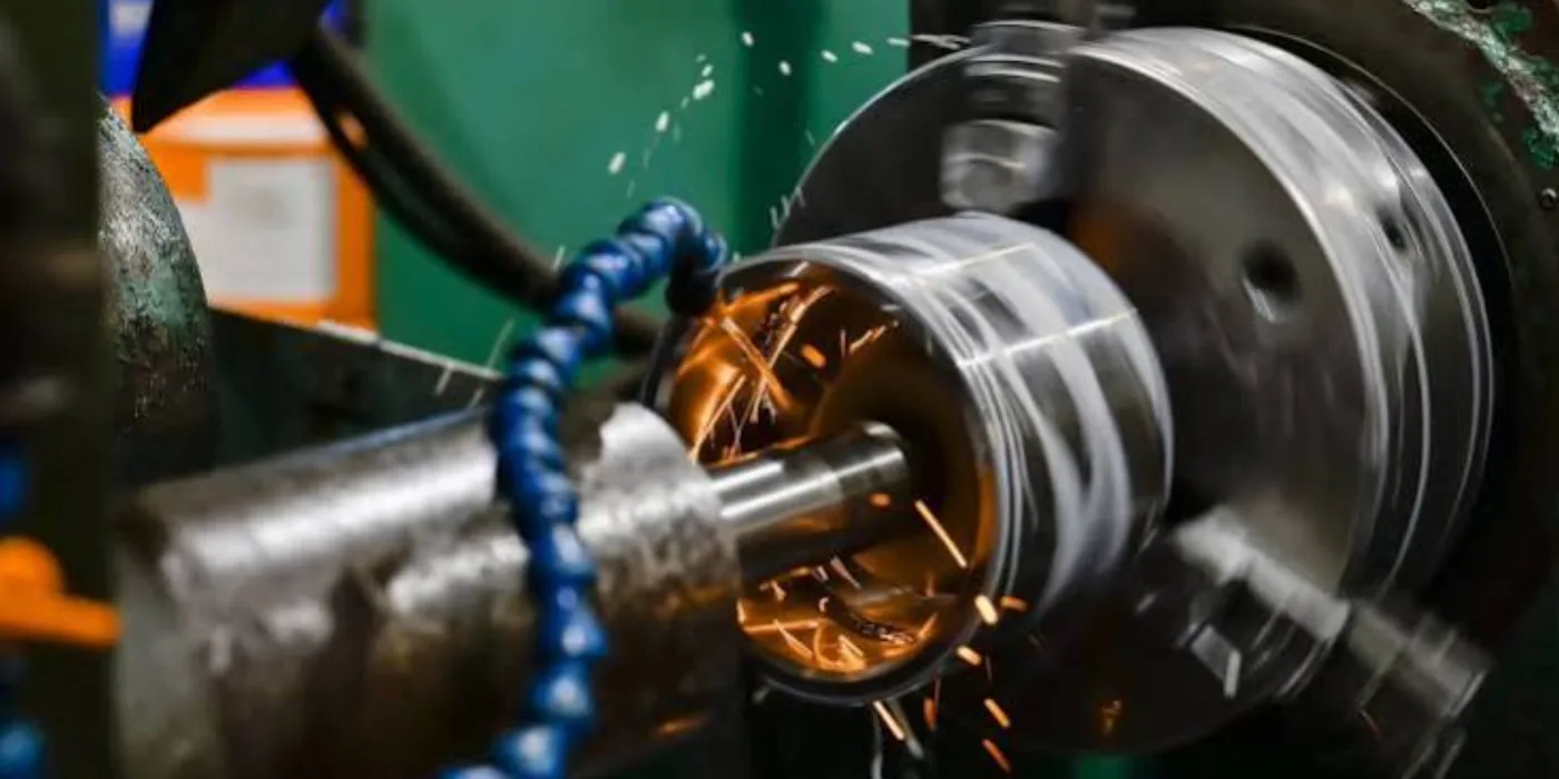
Precision cylindrical grinding of a shaft on a machine tool in the EmersonEIMS workshop, with coolant and sparks
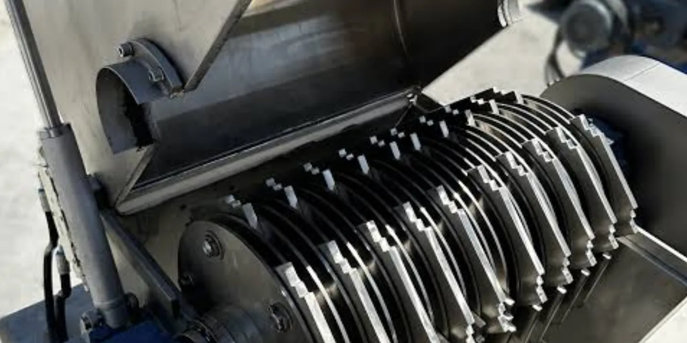
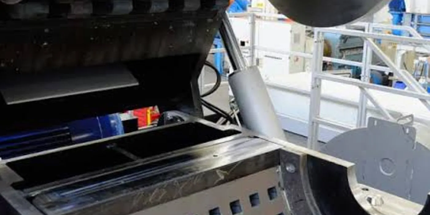
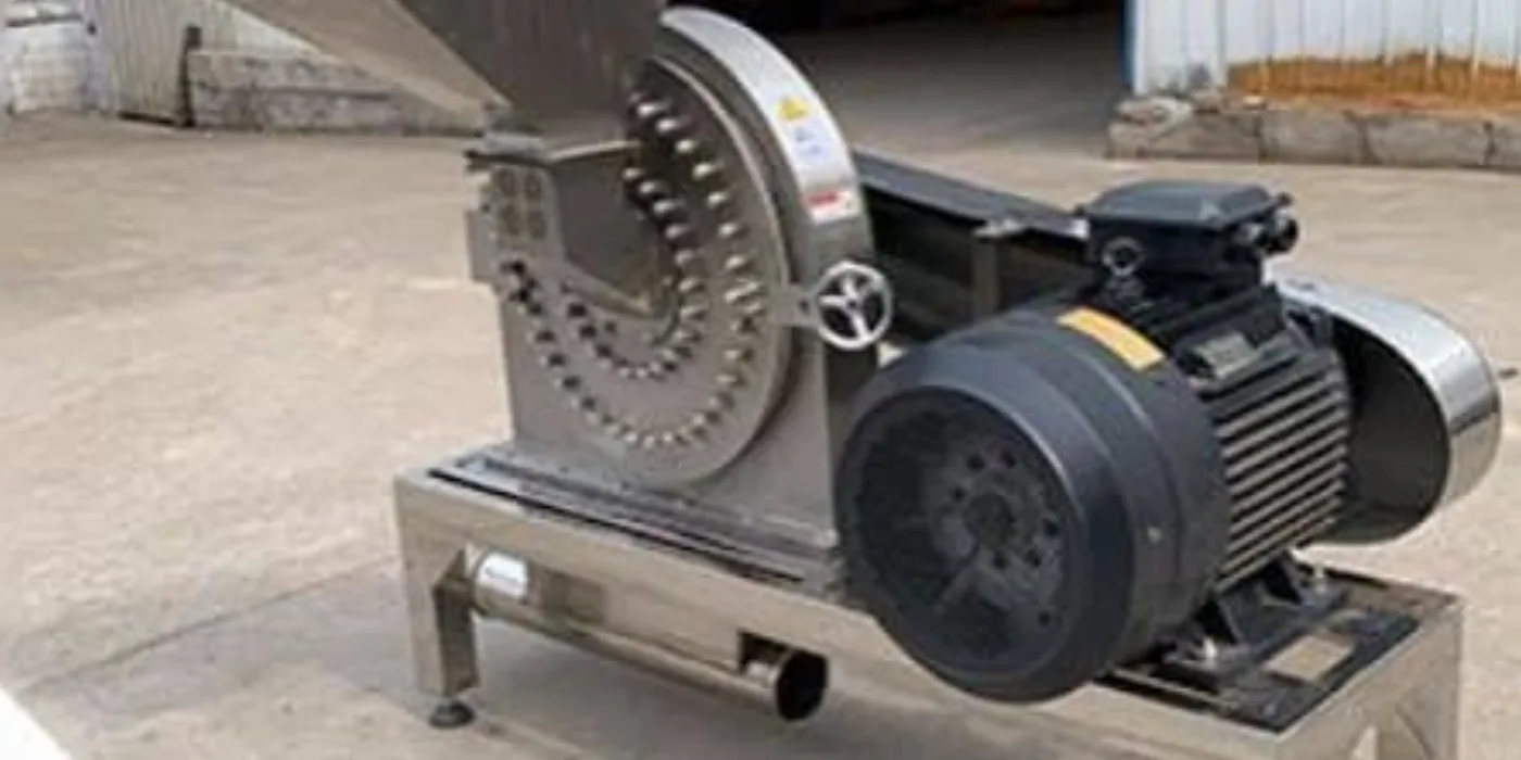
Industrial size-reduction grinder machine with feed chute and drive
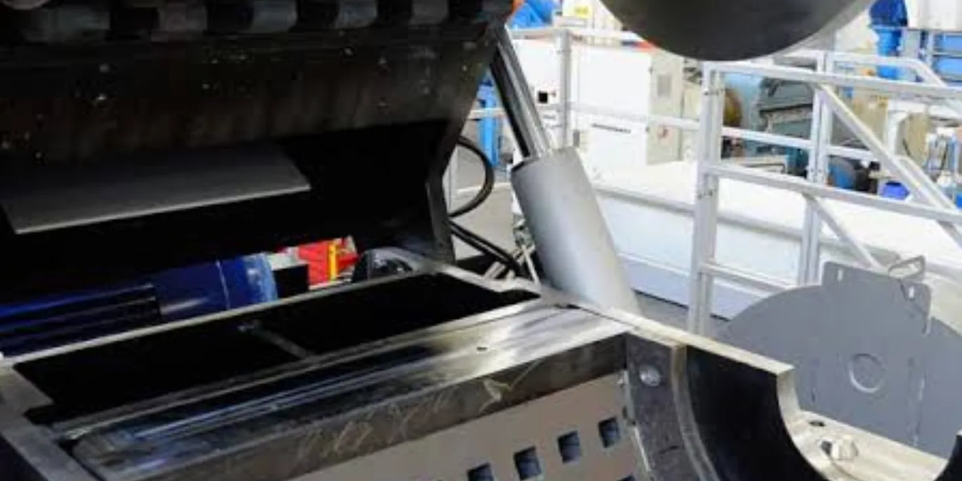
Industrial grinder fabrication and assembly at EmersonEIMS
Grinder machinery components during fabrication

Understanding it

Industrial grinders and size-reduction machines are built to a defined duty — the material, the target particle size and the throughput determine the machine, not the other way round. EmersonEIMS both fabricates grinder/size-reduction equipment and carries out the precision machining (turning, boring and cylindrical grinding of shafts and journals) that keeps rotating machinery true.

Full technical guide — causes, repair, parts & prevention+
Why it fails — common causes
What the enquiry must define
The material to be processed, the required particle or output size, the expected throughput, operating hours, available motor power and supply, the construction material required, guarding needs and the installation location.
Where machining is needed
Worn shafts, journals and bores on pumps, motors and machinery are restored by precision turning and grinding to the correct size and finish — a core workshop capability.
How we repair it
  1. 1.Collect the full duty — material, output size, throughput, hours, motor and supply, construction material, guarding and location — before fabricating or quoting.
  2. 2.Fabricate the machine in the material suited to the process, with the drive matched to the available supply.
  3. 3.For precision work: set up the shaft or component and turn, bore or cylindrically grind to the correct size and surface finish.
  4. 4.Form feed and discharge, fit guarding and safety interlocks.
  5. 5.Support installation and commissioning.
How we test it before handover
  • ✓Precision work: verify dimensions and surface finish to the drawing/specification.
  • ✓Machinery: confirm rotation, balance and safe running, and trial on the intended material.
Parts & materials used
  • Fabricated frame and chamber
  • Drive, motor mounting and guarding
  • Bearings and shafts
  • Wear liners suited to the material
How to prevent it happening again
  • →Do not fabricate or quote from a photograph alone — material and duty details are required first.
  • →Publish no throughput figure that has not been established for the specific machine.

Worth knowing: We do not fabricate or quote machinery from a photograph alone. Material, output size, throughput, operating hours and electrical supply are required first.

Discuss Grinder Requirements

How the workshop process works

The same six stages apply whether the item arrives by courier from Turkana or we attend your plant room in Nairobi.

  1. Stage 1

    Initial enquiry

    You send photographs of the equipment and its nameplate, the brand, model and serial number where available, a description of the fault, your location and any previous repair history.
  2. Stage 2
    Receipt or site assessment

    The component is delivered to our workshop, collected where arrangements are available, sent through an agreed courier or transport provider, or assessed at your site where the work needs field attendance.

  3. Stage 3

    Inspection and diagnosis

    Technicians establish the probable cause of failure, the parts required, whether the item is repairable, any safety concerns, and whether replacement would be more economical than repair.

  4. Stage 4

    Written quotation

    You receive the repair scope and quotation in writing. Major work does not proceed until you have approved it.

  5. Stage 5

    Repair, rebuild or fabrication

    The approved work is carried out with the appropriate materials, procedures and quality checks for the component.

  6. Stage 6

    Testing and handover

    Functional, electrical, pressure or load testing as applicable, with a summary of the work done and the parts replaced, then collection or dispatch by the agreed route.

A site survey and diagnostic fee covers the technician’s attendance, inspection and fault diagnosis. The full fee is deducted from the contract when the work is awarded to EmersonEIMS.

Send your component from anywhere in Kenya

You do not always need to travel to Nairobi to use the workshop. Suitable components can be sent to us by courier, parcel or transport service, and returned the same way once the approved repair is complete.

Transport options

  • •Established courier companies
  • •G4S courier services
  • •Wells Fargo courier services
  • •Matatu and bus parcel services
  • •Regional transport providers
  • •Your own nominated courier

Availability, packaging requirements, liability, insurance, cost and expected transit are confirmed with you before anything is dispatched.

Before you send equipment

  • ✔Drain fuel, oil or coolant where appropriate
  • ✔Protect exposed shafts and terminals
  • ✔Seal injector and pump openings
  • ✔Pack in strong, protective packaging
  • ✔Include your contact details inside the parcel
  • ✔Include the quotation or job reference
  • ✔Photograph the item before dispatch
  • ✔Share the consignment or parcel details with us

Please do not dispatch leaking, pressurised, hazardous or inadequately packaged equipment — it is a risk to handlers and often arrives damaged.

Request an inspection or quotation

Photographs tell us more than a description. Send the equipment and its nameplate on WhatsApp and our technical team will come back to you on inspection, the technical details still needed and the appropriate next step.

Please include

  • •Your name and company
  • •County and nearest town
  • •Service required
  • •Equipment type, brand and model
  • •Serial number from the nameplate
  • •Description of the problem
  • •Whether the equipment still runs
  • •Whether the item is on site or ready to dispatch
  • •Photographs of the equipment and nameplate
  • •Any date you are working towards
Start the enquiry on WhatsAppUse the contact form insteadCall +254768860665

We do not quote a repair price or completion date before inspection. Once we have seen the equipment you get a written scope and quotation, and major work begins only after you approve it.

Frequently asked questions

Can I send a generator component from another county?+

Yes. Components are regularly sent to us from across Kenya by courier, bus or matatu parcel service. Agree the route, packaging and cost with us before dispatch so the item arrives safely and we know to expect it.

Do you repair all generator brands?+

We work across the common industrial diesel brands including Cummins, Perkins, Caterpillar, Volvo, Lister Petter, Iveco and others. Whether a specific component is repairable depends on its condition and parts availability, which we confirm at inspection.

Do you inspect equipment before giving a final repair price?+

Yes. A meaningful price is only possible after inspection. We charge a site survey and diagnostic fee for the inspection, and the full fee is deducted from the contract when the work is awarded to us.

Can you collect equipment from our premises?+

Collection can be arranged in some cases depending on the item, the location and the schedule. Ask when you enquire and we will tell you what is practical for your site rather than promising in advance.

Do you repair both charging alternators and generator alternators?+

Yes, and they are different machines. The charging alternator keeps the starting batteries up; the generator end produces your output. We identify which has failed before quoting, because the work and the cost differ substantially.

Can you rewind an alternator or electric motor?+

Rewinding is offered where it is technically sound and economically sensible. On some smaller machines a replacement costs less than a rewind, and we will say so.

Can every injector, pump or turbocharger be repaired?+

No. Some components are beyond economic repair, and we tell you that at inspection rather than after starting work. Where replacement is the better outcome we recommend it.

Do repaired items receive testing before dispatch?+

Yes, where the equipment and available test facilities allow — functional, electrical, pressure or no-load testing as applicable to the component. The testing done is stated in the handover summary.

Can you fabricate a canopy for an existing generator?+

Yes. The canopy is designed around your machine, its cooling-air requirement and exhaust routing. We do not quote a guaranteed noise figure without acoustic design and measurement.

Can you automate an existing diesel fuel tank?+

Yes. Level monitoring, alarms, automatic bulk-to-day transfer and consumption monitoring can be added to existing tanks. The functions supplied are specified per project.

Do you construct generator plinths at the customer site?+

Yes. The plinth is designed from the actual generator weight and footprint and the ground conditions at your site. There is no universal size.

Can you design a hammer mill for a particular product?+

Yes, provided you can tell us the material, the output size you need, the throughput expected, the motor power available and how the machine will be fed. Those determine the design.

Do you repair UPS systems and battery banks?+

Yes. We diagnose the UPS and the battery bank together, since a serviceable UPS with an exhausted battery bank still fails when mains drops. Repair viability is confirmed after diagnosis.

Can repaired components be returned through a courier?+

Yes. Return is by the route agreed with you — courier, bus or matatu parcel, or your own transporter. We confirm the channel and cost before dispatch and tell you when the item has gone.

What information should I send before requesting a quotation?+

Photographs of the equipment and its nameplate, the brand and model, the serial number, a description of the symptoms, whether the machine still runs, your county and town, and any recent repair history.

Related EmersonEIMS services

Generator salesGenerator repairs & maintenanceGenerator spare partsGenerator installationMotor rewindingDiesel automationSteel fabricationBorehole & pump servicesATS & changeover systemsUPS Intelligence LabGenerator Oracle diagnosticsAreas we coverContact & service booking
🏭

Ready for a Workshop Repair or Fabrication?

From radiator repairs to engine overhauls to custom steel fabrication — our Embakasi workshop is equipped for generators across all brands and sizes.

Or choose a different option:

Need to speak directly?

📞 +254 768 860 665💬 WhatsApp